Scheme
Overview
Here are below the winding scheme user inputs.
 |
|
|---|---|
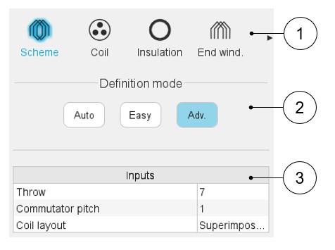
| 1 | Sections to design the winding step by step. |
| 2 | Winding definition mode: Automatic, Easy, or Advanced. See the below section dedicated to the construction of the winding architecture. |
| 3 | List of user inputs to define the winding architecture. See the corresponding definition below. |
Definition modes
There are three winding definition modes: Automatic, Easy and Advanced. See below the corresponding illustration.
Automatic
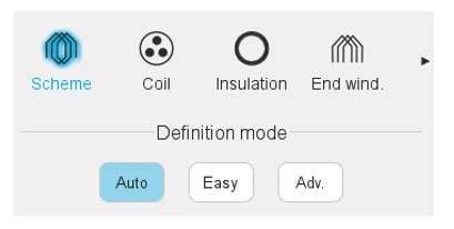
The automatic mode always creates the most basic winding corresponding to the number of poles and slots defining the machine topology. This scheme corresponds to a simplex lap winding with progressive connection. Values for throw and commutator pitch are defined in the table below.
| Basic winding variables | Value in easy mode |
|---|---|
| Throw (coil pitch) | round (number of slots / number of poles) |
| Commutator pitch | 1 |
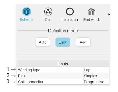
Easy
 |
|
|---|---|
| 1 | Selection of winding type. Lap: The ends of one coil are connected to consecutive commutation segments (i.e., the commutator pitch absolute value is equal to 1 for simplex winding). Wave: The ends of one coil are connected to commutator segments separated by an angular distance as close as two pole pitch as possible (for simplex winding). |
| 2 | Selection of the plex. The plex is a measure of how many
commutator segments can touch a particular brush at the same time.
The number of parallel paths in the machine circuit is directly
proportional to its plex. Even if there is not a theoretical limitation to its value, for practical designs three plex are considered: simplex (plex=1), duplex (plex=2) and triplex (plex=3). |
| 3 | Selection of coil connection: Progressive or
regressive Progressive connection: Commutator segments are connected following the same direction as winding (i.e., commutator pitch is positive). Regressive connection: Commutator segments are connected following the opposite direction as winding (i.e., commutator pitch is negative). An illustration of these two types of winding is given in the next sections. |
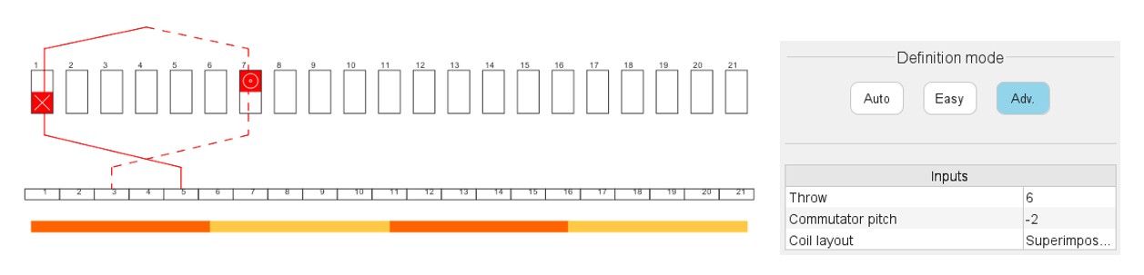
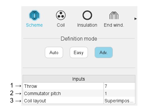
Advanced
 |
|
|---|---|
| 1 | Selection of the thrown (coil pitch) The proposed solutions depend on the number of slots and the number of poles. Throw <= ceil (number of slots / number of poles) |
| 2 | Commutator pitch. Number of commutator segments between the
segment connected to the coil input and the segment connected to the
coil output. Only the options compatible with a valid lap/wave winding are offered. |
| 3 | Definition of the coil layout i.e. how the coil sections are
distributed into the slot. The two possible choices are:
By default, the superimposed option is selected. |