Mesh concept
AC currents in conductors: skin effect / proximity effect
The basic assumption of the PEEC method for partial inductances evaluation is that the current density is uniform in the conductor cross-section, and that a privileged path of the electric current is identified.
However, these assumptions restrict the applicability for solid conductors, because:
- at high frequencies the current density is distributed towards the periphery of conductors – the skin effect
- each conductor influences its neighbor and contributes to the redistribution of the current lines and to the change of the resistive, inductive and mutual behaviors – the proximity effect
Solution: the mesh
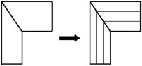
The chosen solution to take into account the skin and proximity effects in solid conductors is to subdivide the conductor into several elementary conductors in which the current density is assumed to be uniform over the cross-section area, in order to apply the previously defined formulas.
This stage, which we called mesh, is then essential to guarantee the accuracy of the results in the case of solid conductors.
The computation principle, with meshing, is presented by means of a simple example in the following block.
Principle (example)
The interest lies in the computation of the equivalent impedance of a bent tubular conductor of rectangular cross-section (at a given frequency). The computation principle is presented in the table below.
| Phase 0 (initial phase): the conductor meshing | |
|---|---|
| Splitting of conductor into elementary
tubes (1D elements)
|
Association of a (R, L) couple of
parameters to each 1D element
|
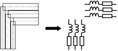
| Phase 1: PEEC computation, independent of frequency |
|---|
|
Computation of the resistances and partial self-inductances (R, L) of each element Computation of the partial mutual inductances (M) among all the parallel elements |
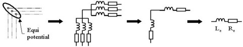
| Phase 2: computation of the equivalent impedance (depending on frequency) |
|---|
| Construction of an equivalent circuit by
series/parallel connection of elements
Computation of the resistance and equivalent inductance (Re, Le) of the tubular conductor for a given frequency (f) |
Different meshes for different conductors
It is possible to distinguish various meshes for different geometries of the conductor.
The 1D and 2D meshes are presented in the table and are detailed below in the following paragraphs.
The 3D mesh would allow one to model the solid conductors in which the path of the current would not be known (not yet implemented in Flux PEEC).
| The mesh | is used for conductors | The cutting is realized … | |
| of … shape | in which … | ||
| 1D | tubular |
it is possible to identify a privileged path of the current flow (unidirectional current) |
in the cross-section of tube |
| 2D | plate |
it is not possible to identify a privileged path of the current flow (bidirectional current) |
in the plane of the current flow |