1D mesh
Introduction
The mesh known as 1D for the tubular solid conductors is chosen if it is possible to identify a privileged path of current flow.
It is mainly the case of distribution current bus-bars, the tracks of printed circuits, the connections inside the power electronic modules, …
Principle
In the case of a 1D mesh, the conductor is split into elementary conductors of smaller cross-section (see figure below).
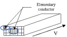
(An elementary conductor is a 1D element of mesh where the current has a privileged direction of flow: principal direction of the tube).
An elementary conductor is modeled by using a partial electric circuit (see figure below), in which the current density is uniform.
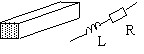
With the previously described analytical formulas, it is possible to calculate: the partial resistance (Ri) and the partial inductance (Li) for each elementary conductor.
The computation of the partial mutual inductances (Mij) between different elementary conductors can be done by the analytical formulas if conductors are parallel. However, if they are positioned at an angle it is necessary to use the semi-analytical formulations.
Equivalent electric scheme
The equivalent electric scheme of a tubular solid conductor is obtained by associating (in parallel) the partial electric circuits of the elementary conductors.
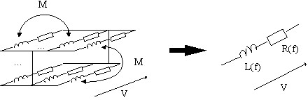
The values of parameters of the equivalent electric scheme depend on the frequency, because the skin and proximity effects affect the mutual couplings between the elementary conductors.
Different types of mesh
There are different ways to mesh the section of 1D conductors. The choice depends on the shape of the cross-section profile, as well as on the accuracy of the results that the user wishes to obtain.
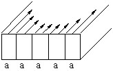
The uniform and geometric meshes are the two most commonly used meshes for the conductors of a rectangular cross-section profile.
However, conductors of any cross-section are meshed either in a uniform manner or by means of so-called ‘non-conform' technique.
The main characteristics of different types of mesh are presented in the table below.
| Type | Description | Use |
|---|---|---|
| mesh with uniform elements | all elements have the same
cross-section
|
low frequency |
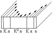
| mesh with geometric elements | the elements on the edge have smaller
cross-section (K > 1)
|
high frequency |
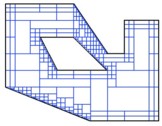
| non-conform mesh | the elements have width and thickness
variable in order to fit well to the cross-section
|
variously shaped cross-section |
Criterion for the mesh
Criterion:
In order to obtain correct results, the thickness of an element must be less or equal to the skin penetration depth.
A mesh with uniform elements can lead to a great number of elements (and to significant memory requirements) at high frequency.
The geometric element allows a mesh with much thinner elements at the exterior of the solid conductor. This type of mesh gives the best results, since the density of elements is larger on the circumference of the solid conductor, where the current density varies most, and weak in the center, where the current density is almost constant.
The non-conform mesh is well-adapted to the conductors of variously-shaped cross-section without increasing the size of the problem. Being adjustable with the frequency, such meshing technique is well-adapted at both low and high frequencies.