Since version 2026, Flux 3D and Flux PEEC are no longer available.
Please use SimLab to create a new 3D project or to import an existing Flux 3D project.
Please use SimLab to create a new PEEC project (not possible to import an existing Flux PEEC project).
/!\ Documentation updates are in progress – some mentions of 3D may still appear.
New example
As a reminder, all examples are accessible via the Flux supervisor, in the context of Open an example.
| Examples | Description | |
|---|---|---|
| Foil Coil 2D application note |
This example concerns the creation of a coil conductor region with losses and detailed geometrical description to represent a foil coil. Geometry, meshing, physics definition and solving will be automatically carried out by dedicated set of macros which takes as inputs the material properties and the geometrical features of the machine.A foil coil is a winding obtained from a thin, rectangular, metallic sheet folded in a spiral-like shape, as shown in Figure 1. The sheet is covered by an insulating coating (varnish). This kind of coil design is common in electromagnetic devices such as power transformers and actuators. 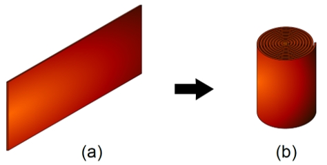 Figure 1: A thin metallic sheet (a) folded in the shape of a foil coil (b) The current density distribution in a foil-wound coil fed by a time-varying source depends on skin and proximity effects. Since the foil is usually very thin and made from a material with a high electrical conductivity, the skin effect along its thickness is negligible (i.e., the current density in each turn results practically uniform along a radial direction). On the other hand, the current density in each foil turn may greatly vary along the axial direction of the coil as a function of both position and frequency. This anisotropic behavior is specific to foil coils and influences the Joule losses developed in the bulk of the coil material. Thus, Flux implements a special homogenization technique to efficiently represent it in its 2D Steady State AC Magnetic application. This technique is exclusive to foil coils and differs from the approach used in the other subtypes of coil conductor regions with losses and detailed geometric description representing stranded coils. |
|