Alternative workflow with Flux meshing tools
Introduction
If user is not satisfied by mesh obtained by the macro, it is possible to use Flux meshing tools. But it requires some user operations on both geometry and mesh and it works only with simple conductors shapes.Step by step
The operations to follow to obtain a skin effect mesh with Flux meshing tools are
presented:
- Create the lines to define the skin depth. Flux meshing tools will be assigned to those lines.
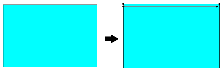
- Assign the mesh data to impose the number of layer in the skin depth:
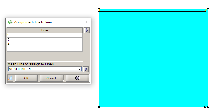
- Create a "Mesh Line" through . Choose Arithmetic, and enter the number of layers.
- Assign this Mesh Line to the lines through . Select the lines in the skin depth and the
previously created meshline:
- Assign the mesh data to impose rectangular elements in the skin depth:
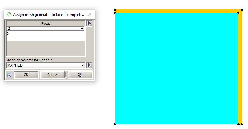
- Assign the MAPPED mesh generator (available
by default) to the faces in the skin depth, through . Select the faces in the skin depth and the MAPPED
mesh generator:
- Assign the MAPPED mesh generator (available
by default) to the faces in the skin depth, through . Select the faces in the skin depth and the MAPPED
mesh generator:
- Optionnal: It is possible to change the mesh progression on the tranversal direction by, for example, assigning a meshline or unassigning the relaxation on the lines, etc.
- Mesh the device through Note: In 2D, the second order elements are generated automatically.
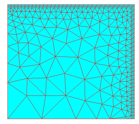
Here is an example of the mesh obtained with this workflow (3 layers):