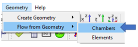
Flow from Geometry - Chambers
You can load geometry from a CAD program into the graphical user interface and use it to create the flow model. The geometry is also useful for visualizing what the chambers and elements represent in the flow model. Use the function to read geometry in IGES or STEP format.
A vertex (point or 0D CAD element) is useful for placing flow chambers. You can use the flow chambers to create flow elements.
Select one of the following methods to use the vertex to locate a flow chamber:
- Create the chamber and vertex simultaneously. From the Create Vertex window, select Create chamber.
- Press Shift while dragging a chamber from the Element Library. The vertices are automatically displayed, and the chamber can be snapped to a vertex.
- Use to create chambers on vertices. This method is described below.
Create Chamber Methods
- Next to the chamber creation method, click Create or
Define to create the vertices. Note: Define the Options before clicking Create.
- Set the Chamber Type before clicking
Create or Define.
Figure 2. 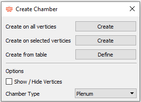
- Select one of the following methods to create a chamber:
- Create on all vertices
- Creates a chamber on every vertex in the model.
- Create at selected vertices
- Creates a chamber at the selected vertices. Click Create to display the vertices and select them. To end the selection mode for this option, close the window or Create again.
- Create from table
- Creates a chamber at the X,Y,Z locations in the table. A table of X,Y,Z coordinates can be copied and pasted into this table from another program (such as a spreadsheet editor).
Figure 3. 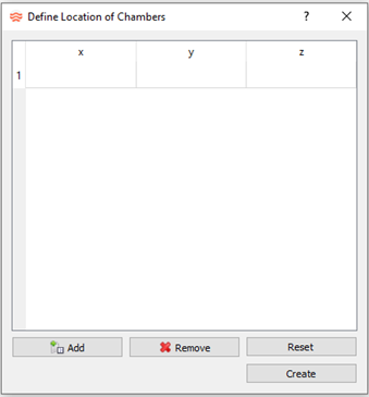
- Additional options include:
- Show/Hide Vertices
- Select to display existing vertices, or leave unchecked to
hide them. Note: During the creation process, existing vertices are displayed, even if the option is not selected.
- Chamber Type
- Select the chamber type to create.