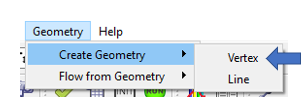
Create Geometry - Vertex
You can load geometry from a CAD program into the graphical user interface and use it to create the flow model. The geometry is also useful for visualizing what the chambers and elements represent in the flow model. Use the function to read geometry in IGES or STEP format.
A vertex (point or 0D CAD element) is useful for placing flow chambers. Use the flow chambers to create flow elements.
Select one of the following methods to use the vertex to locate a flow chamber:
- Create the chamber and vertex simultaneously. From the Create Vertex window, select Create chamber.
- Press Shift while dragging a chamber from the Element Library. The vertices are automatically displayed, and the chamber can be snapped to a vertex.
- Use to create chambers on vertices.
Follow these steps to move an existing chamber or thermal node (Tnode) to an existing
vertex:
- Select the chamber (or Tnode) to be moved.
- Press the “V” key to display the existing vertices in the model.
- Select the vertex for the chamber (or Tnode) location.
Create Vertex Methods
- From the Create Vertex dialog, next to vertex creation method, click
Create to create the vertices.Note: Define the Options before clicking Create.
- Select Create chamber to create chambers and the vertex simultaneously.
- Select the Chamber Type before clicking
Create.
Figure 2. 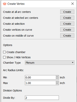
- Use one of the following methods to create a vertex:
- Create at all arc centers
- Creates a vertex at every arc center, with an arc radius between the Arc Radius Limits, specified under Options.
- Create at selected arc centers
- Creates a vertex at the selected arc centers. Click Create; the geometry changes color to indicate that curves are ready to be selected.
- Create at selection
- Creates a vertex on a curve at the location where the curve is selected.
- Create vertices on curve
- Creates evenly spaced vertices on the selected curve. The number of vertices depends on the number in the Divide By field under Options. For example, Divide by 2 places three vertices on the curve, separated by the curve length divided by 2.
- Create on middle of curve
- Creates one vertex on the selected curve. The vertex is at 50% of the arc length of the curve.
To end the selection mode for options two through five above, close the window or click Create again.
- Additional options include:
- Create chamber
- Select to create a chamber and vertex, or leave unchecked to only create a vertex.
- Show/Hide Vertices
- Select to display existing vertices, or leave unchecked to hide them.
- Arc Radius Limits
- Controls the arcs used to create vertices for the Create at all arc centers option.
- Divide By
- Controls the number of evenly spaced vertices that are created on a curve for the Create vertices on curve option.