Solver Strategies
Solver Basics
1D flow solvers use an iterative procedure to solve for the restriction flow rates and non-boundary pressures. This simplified flow chart shows the iterative procedure but does not show all the complexities involved.
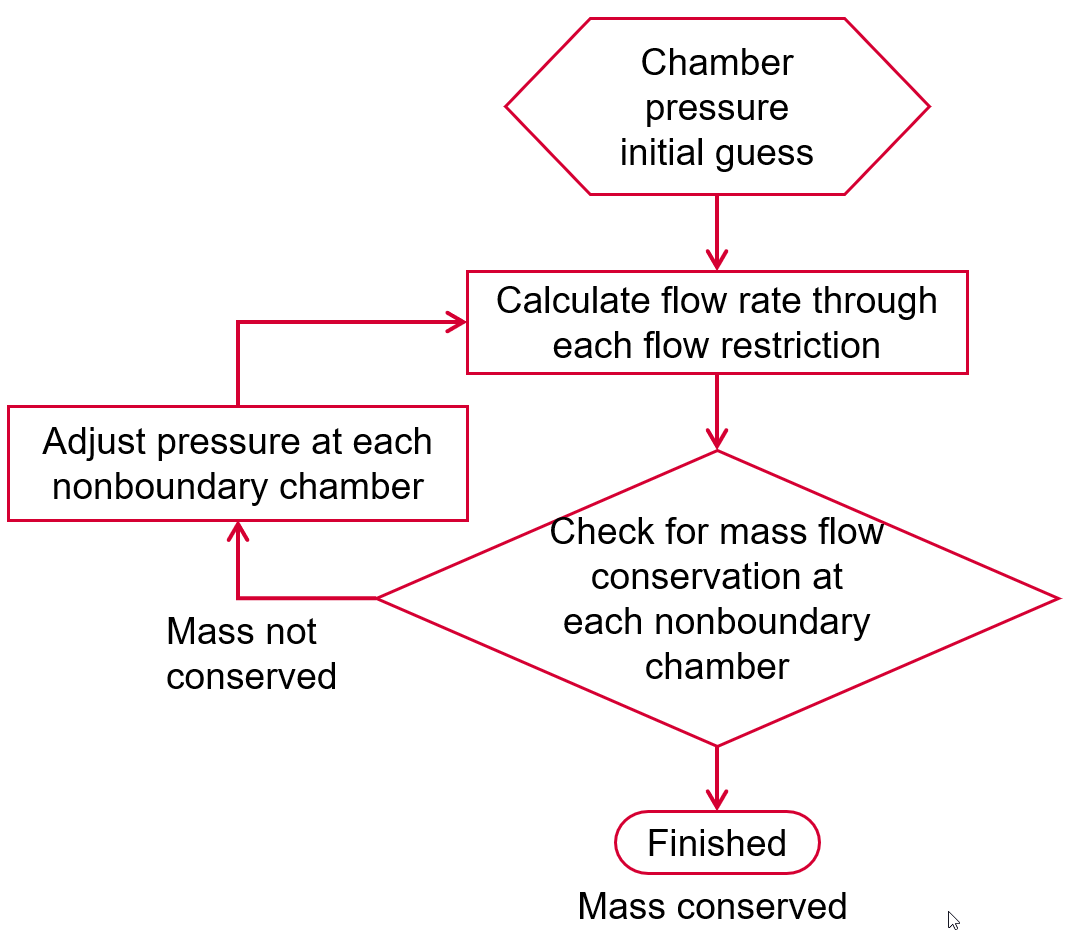
The key part of the flow solver is the pressure adjustment step “Adjust pressure
at each non-boundary chamber. Each element returns a derivative ![]() that tells the solver how to change the
pressure
that tells the solver how to change the
pressure
- Derivatives based on element type and geometry.
- The pressure change per iteration may be less than the derivative specifies (damping)
Convergence
Flow solver convergence determined by
- Mass flow continuity at each chamber (Mass flow continuity in each chamber is the primary convergence criteria in the flow solver.)
- Chamber temperature, pressure, swirl, and velocity change has stabilized
- Elements converged
- Some elements have internal loops for momentum and energy balance
Thermal solver convergence determined by
- Heat flow balance at the thermal nodes
- Node temperature has stabilized
Flow Solver Convergence Controls
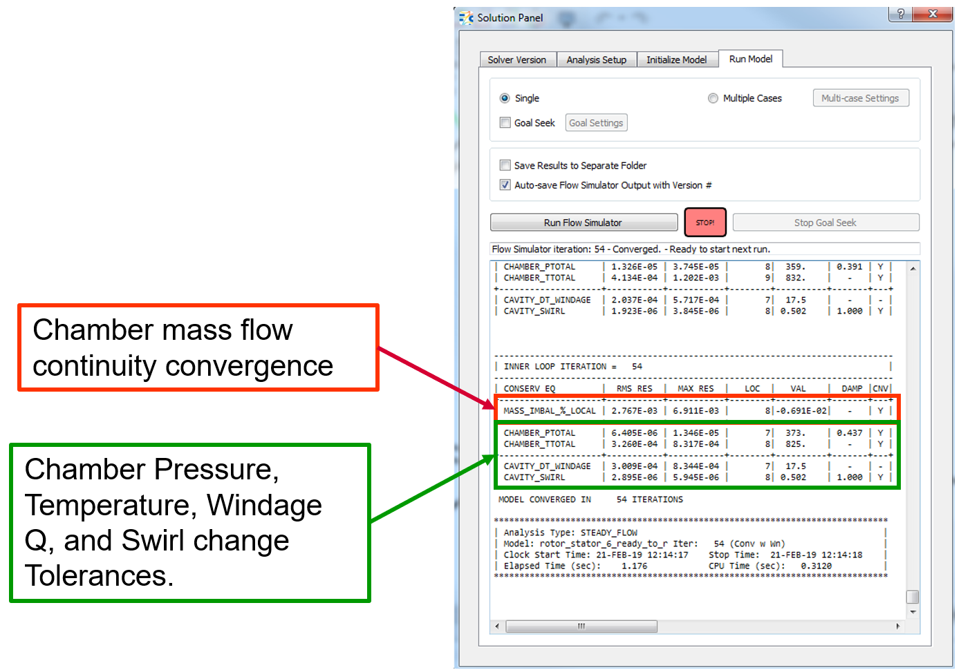
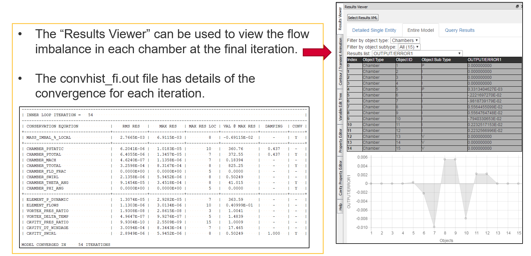
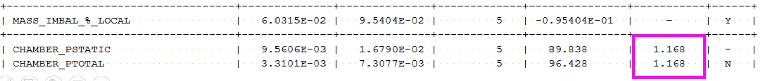
Monitor Convergence during run
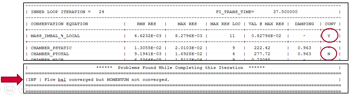
The “CNV” column in this window has a “N” if the item is not converged and “Y” if the item is converged.
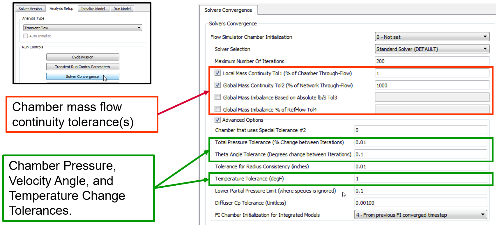
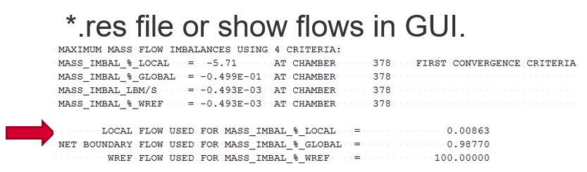
Chamber Mass Flow Continuity
The 4 different mass continuity options differ in the value that’s used in the denominator of the error equation. Error1 can be the most severe since the Error can be large if the chamber thru-flow is very low even if the imbalance is low in terms of lbm/sec. User can use the option they feel gives them accurate results and good run time.
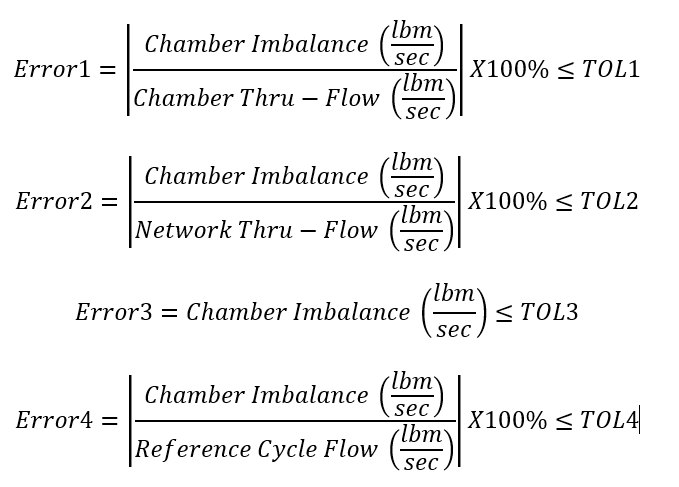
- Error 1 Default = 1% But should be reduced as far as possible (0.1% or 0.01% are good).
- Error2, 3, or 4 can be used if you model has convergence problems using Error1.
- 2 options can be used: both must be satisfied for convergence
- If only 1 option is needed set 2nd option set to a high value (like 1000)
- The Reference flow rate for Error4 is set in the Analysis Setup→ Reference Conditions → Reference Flow Rate (lbm/sec).
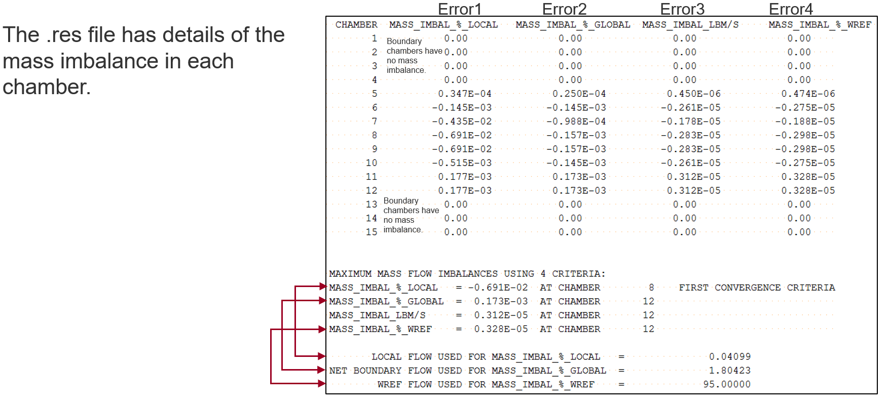
Inspect Convergence After Run
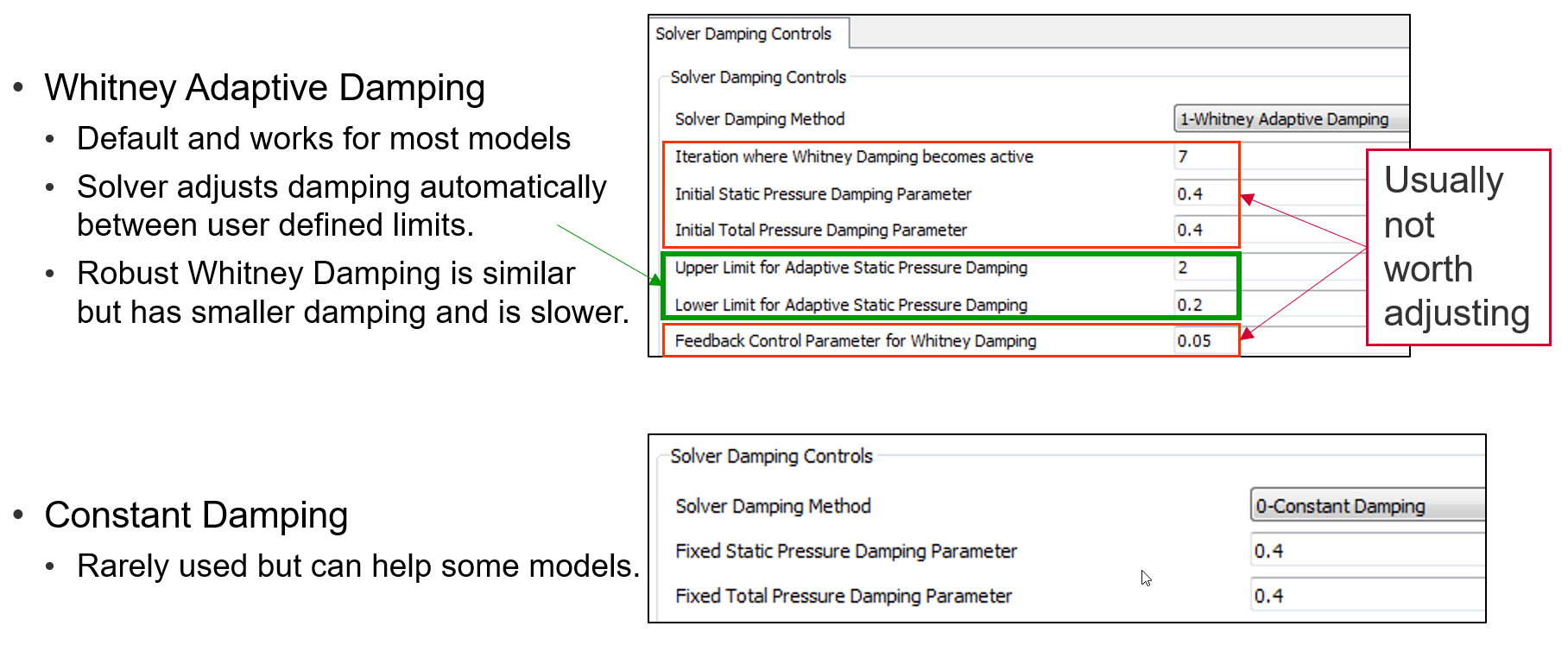
Damping
Inversion of the Flow Simulator solution matrix at each iteration step yields the Newton-Raphson step sizes for each chamber static pressure. DAMPS is used as a scale factor, which is often less than one, and thus provides a more conservative step towards the solution than standard Newton-Raphson method. This improves robustness and convergence properties in the face of the non-linear and discontinuous behavior of the flow equations.
- The pressure change per iteration can be controlled with damping.
- The lower the damping the less of the change that the flow imbalance calls for will be used.
- Damping can be between ~0 and 2.
- Very low values (~0) have very slow runs
- Very high values (~2) are unstable.
- The damping defaults work for most models.
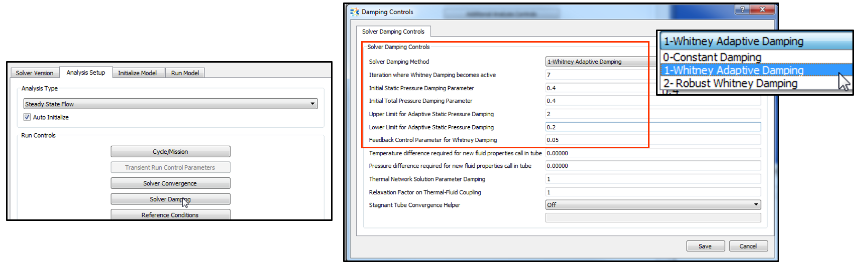
Damping Options
Troubleshooting Solver Problems
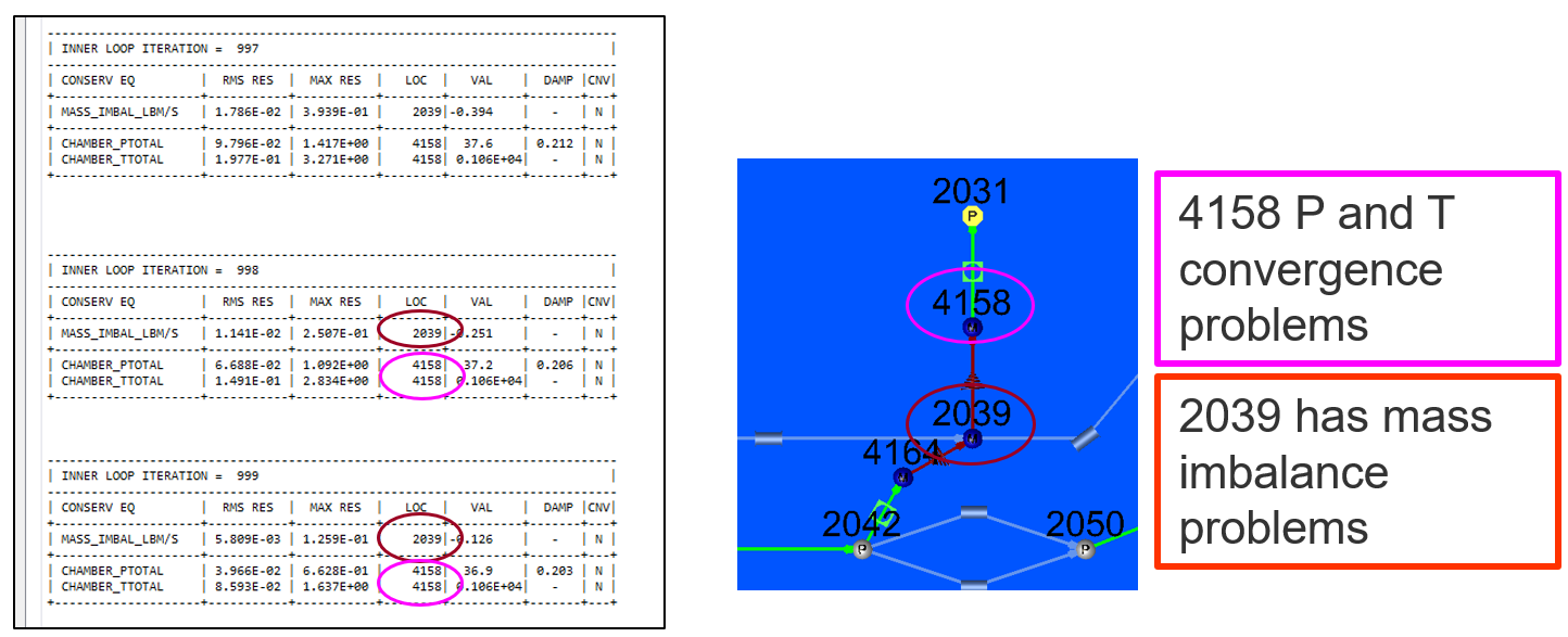
Identify problem chambers
The first thing to do for a model that does not converge is to check for model problems. Check warning section of convhist_fi.out and the GUI checker. If checks are OK, identify the chambers that are having convergence trouble.
![]()
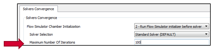
Are Convergence Criteria appropriate?
Bigger models usually need more iterations than smaller models. Models typically converge in < 1000 iterations. Only reason models may take more than 1000 is either very large model size or the damping is set to very low values. PID controllers also increase the number of iterations required.
- Is the convergence getting better each iteration?
- Check the convhist_fi.out file for convergence history if needed.
- If yes, increase the number of iterations (or damping)
- Is flow continuity Error1 being used?
- If yes check the chamber that has continuity problems.
- If it has small through flow consider change to one of the other 3 flow continuity options.
- Is flow converging but something else not converging?
- Perhaps the chamber pressure change convergence tolerance is too low.
Trouble Shoot Convergence Problems: Vortex Elements
If a model has vortex elements and it does not converge check the list at the bottom of convhist_fi.out. If vortex elements reverse direction (flip) often this indicates instability in that portion of the model.
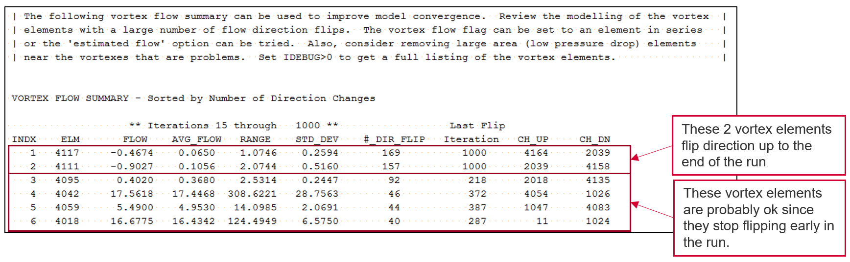
Flow in vortex elements depends on the flow imbalances in the chambers attached to the elements. This has several options:
- Automatic: (Default) Finds the most stable option of Avg up and Down, Upstream, and Downstream
- Average Up and Down: use mass imbalance at both end of the vortex element
- Upstream: Just use the upstream end flow imbalance
- Downstream: Just use the downstream end flow imbalance
- Estimated Flow: Uses static based approach and damps results. This is usually best option for troublesome elements.
- Other: Use the flow directly from another element. The other element must be in series with the vortex element.
Often experimenting with the vortex element flow flag can help convergence of models. The “Estimated Flow” option can be helpful for vortex elements in troublesome parts of the model.
Trouble Shoot Convergence Problems: Damping
Inspect the pressure damping listed in the convhist_fi.out or in the GUI run window.
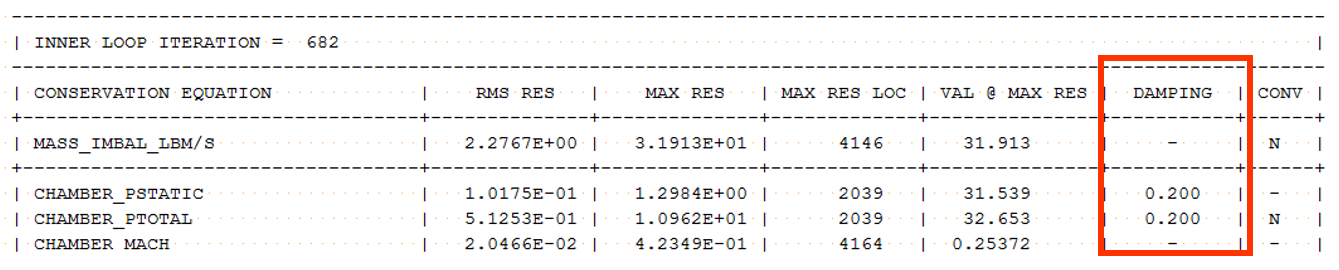
If the damping is stuck at the minimum value then consider reducing the lower damping limit.
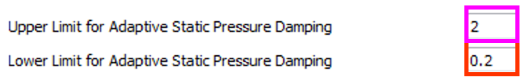
If the damping is staying high (near or above 1) and the model is not converging then consider reducing the upper damping limit.
As a last resort a constant damping with a low value can be used. This is usually slow and requires more iterations.
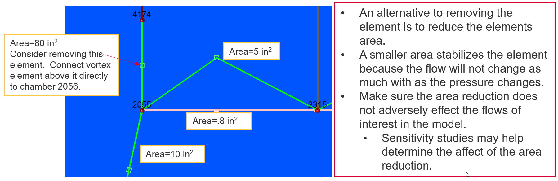
Trouble Shoot Convergence Problems: Model Simplification
Check element restriction areas around chambers that are not converging. If any elements have a much larger area than surrounding elements, consider removing the element. The element probably has a very small pressure drop and velocity (check the non-converged result). Removing it should have a minimal effect on results.
Trouble Shoot Convergence Problems: Initial conditions
Most steady state models are not sensitive to the accuracy of the initial conditions. If you believe the initial conditions are a problem, you can manually change the Pressure and Temperature of the internal chambers before launching a run. Change the pressures so that elements having trouble will flow in the expected direction. Initial conditions for transient analysis must be accurate unless a steady state is done prior to the transient.
Trouble Shoot Convergence Problems: Combustion Modelling
Combustor models can be difficult to converge since diffuser and combustion elements are not as robust as other element types. Typically, don’t want any elements reversing in a combustor.
- Hot gasses flowing where it should not.
- Diffusion and combustion elements may not recover from reverse flow.
- Fixed Flows at the model exits help specify flow direction.
- Specified flows must be physically possible.
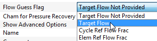
Can use a flow guess for diffuser elements to help element start with forward flow.
- Diffuser losses (K or Cp) must be appropriate.
- Boundary conditions (P and T) must be physical.
- Flow areas and losses through the swirler cup and liner must be reasonable.
- Based on previous combustors
- May need to adjust areas for new designs to achieve convergence.
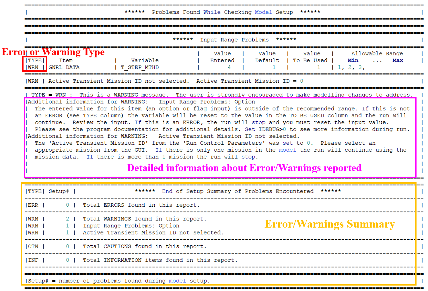
Errors & Warnings in Convhist_fi.out file
The ‘convhist_fi.out’ file contains error and warning messages that occur during the model read operation and during the first and the final iterations of the run. It is intended to enable the user to debug errors in the model and to diagnose other problems that may occur. There errors & warnings are categorized into four types. They are
TYPE = ERR : This is an ERROR message and must be fixed. The run will be terminated.
TYPE = WRN : This is a WARNING message. The user is strongly encouraged to make modelling changes to address.
TYPE = CTN : This is a CAUTION message. The user should consider modelling changes to address this.
TYPE = INF : This is an INFORMATION message. No modelling changes needed.
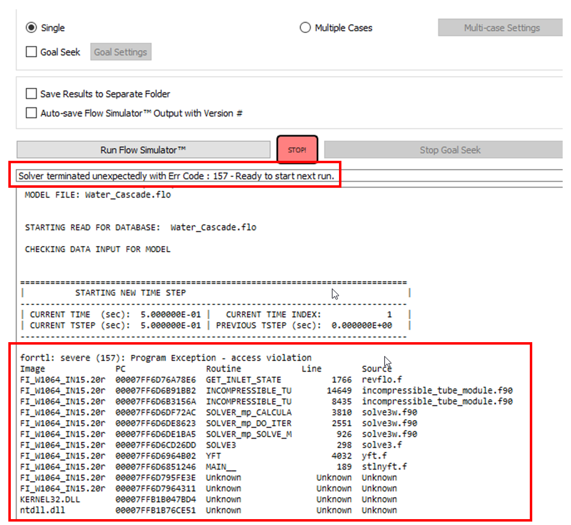
During solver iteration, if the solver stops due to runtime errors, the trace back gets printed on the output window with error codes. You can check the details of run time Fortran error codes from here.