General Data Variables
General Data Variables
In the Flow Simulator model database, the “General Data” section follows the “Chamber Data” section and precedes the “Element Data” section. The following table presents all the general data variables along with descriptions. The index column on the left side indicates the entry sequence number of the variable in the “General Data” section. Most of the default values shown in the following table are suggested. The Flow Simulator solver uses the value in the model file.
| Index | UI Name (. flo label) | Description |
| 1 |
Local Mass Continuity Tolerance #1 (% of Chamber Through-Flow) Tol1
(Tol1 values are written to “TOL1” .flo Field)
Global Mass Imbalance Based on Absolute Mass Flow Rate (Lbm/sec) Tol3
(Tol3 Values are written with “-ve” sign to TOL1 .flo Field) |
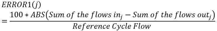
Tol1: Maximum acceptable flow error in any non-boundary chamber for the model to be considered 'converged' where flow error in chamber 'j' is defined by the equation:
This is mass balance as a percentage of the average through flow. By default , TOL1 is the primary flow error tolerance variable. (Default TOL1 = 1%) But should be reduced as far as possible (0.1% or 0.01% are good). Tol3: Maximum acceptable flow error in any non-boundary chamber for the model to be considered 'converged' where flow error in chamber 'j' is defined by the equation
Error1 can be the most severe since the Error can be large if the chamber thru-flow is very low even if the imbalance is low in terms of lbm/sec. TOL3 can be used if you model has convergence problems using Error1. |
| 2 |
Global Mass Continuity Tolerance #2 (% of Network Through-Flow) Tol2
(Tol1 values are written to “TOL1” .flo Field)
Global Mass Imbalance % of Ref Flow Tol4
(Tol4 Values are written with “-ve” sign to TOL2 .flo Field)
|
Tol2: Maximum acceptable flow error in any non-boundary chamber for the model to be considered 'converged' with flow error in chamber 'j' based on the following equation:
This is mass balance as a percentage of the total flow into and out of all boundary chambers. By default, TOL2 is the secondary flow error tolerance variable. Since ERROR2 is based on the boundary flows rather than the local chamber, TOL2 should be more easily satisfied than the same value of TOL1. In those cases where some chambers have small flows, which are possibly unimportant to the user, TOL2 is a useful means of solving a model to within acceptable engineering accuracy. (Default value = 1000.) TOL2 may also be used as an alternative to TOL1 when the variable TOL2_CHAM is set. The use of TOL2 in this option is explained in the TOL2_CHAM description.
Tol4: Maximum acceptable flow error in any non-boundary chamber for the model to be considered 'converged' where flow error in chamber 'j' is defined by the equation
The Reference flow rate for Error4 is set in the Analysis Setup → Reference Conditions → Reference Flow Rate (lbm/sec) User can use the option they feel gives them accurate results and good run time. |
| 3 |
Chamber that uses Special Tolerance #2 (TOL2_CHAM) |
Flag that activates the alternative use of the convergence input variable TOL2. The purpose of this variable is to allow declaration of convergence of models that, based on TOL1, would converge except for local chambers that are extremely slow (or impossible) to converge but are in areas of the model not critical to the analysis or in low flow areas where large percentage mass discontinuities are not critical.
The approach for its use is to select a chamber that is normally slow to converge, as judged by ERROR1, but is not in the “trouble” zone. The idea being that when the selected chamber meets convergence tolerance, all the important chambers are converged. The selection of an appropriate chamber can be tricky so this option should be used with care.
TOL2 is then input as a value substantially smaller than TOL1 and TOL2_CHAM is set to plus or minus AAAA.BBB where AAAA is the number of the selected reference chamber and BBB is the iteration after which the model will be allowed to declare convergence if ERROR1 in the reference chamber is less than TOL2. This declaration of convergence will be independent of convergence in all other chambers. Convergence would also be declared if all chambers meet TOL1 tolerance with their ERROR1 values.
With positive values of TOL2_CHAM, convergence can only be declared if all cavities (if any) have converged. Negative values serve as a flag that declaration of convergence is independent of cavities. (Default value = 0000.000 means that the TOL2_CHAM criteria is not used) |
| 4 |
Static Pressure Damping Parameter (DAMPS)
|
Damping factor for the iteration-by-iteration adjustment of the calculated change in static pressure at each internal chamber.
Inversion of the Flow Simulator solution matrix at each iteration step yields the Newton-Raphson step sizes for each chamber static pressure. DAMPS is used as a scale factor, which is often less than one, and thus provides a more conservative step towards the solution than standard Newton-Raphson method. This improves robustness and convergence properties in the face of the non-linear and discontinuous behavior of the flow equations.
The optimum values for DAMPS and DAMPT are model dependent. Values between 0.3 and 1.0 are commonly used. Values greater than one are used when the maximum errors become progressively smaller on successive iteration steps. (Default value = 0.4) |
| 5 |
Total Pressure Damping Parameter (DAMPT) |
Damping factor for the iteration-by-iteration adjustment of the calculated change in total pressure at each internal chamber.
Inversion of the Flow Simulator solution matrix at each iteration step yields the Newton-Raphson step sizes for each chamber total pressure. DAMPT is used as a scale factor, which is often less than one, and thus provides a more conservative step towards the solution than standard Newton-Raphson method. This improves robustness and convergence properties in the face of the non-linear and discontinuous behavior of the flow equations.
The optimum values for DAMPS and DAMPT are model dependent. Values between 0.3 and 1.0 are commonly used. Values greater than one are used when the maximum errors become progressively smaller on successive iteration steps. (Default value = 0.4) |
| 6 |
Reference Flow Rate (WREF)
|
Reference mass flow rate (lbm/s). Element flow rate results will be presented in the output files both in terms of absolute flow rate in lbm/s and as a percentage of the reference flow rate, WREF. (Default value = 1.0) |
| 7 |
Shaft #1 Rotor Speed (RPM) (ELERPM1) |
First global reference rotational speed (RPM). The value for ELERPM1 will be used whenever an element selector variable RPMSEL, RPMSELR, or RPMSELL has a value of 1.0 and whenever a chamber or vortex RTR_IDX variable has a value of 1. (Default value = 0.) |
| 8 |
Shaft #2 Rotor Speed (RPM) (ELERPM2) |
Second global reference rotational speed (RPM). The value for ELERPM2 will be used whenever an element selector variable RPMSEL, RPMSELR, or RPMSELL has a value of 2.0 and whenever a chamber or vortex RTR_IDX variable has a value of 2. (Default value = 0.) |
| 9 |
Shaft #3 Rotor Speed (RPM) (ELERPM3) |
Third global reference rotational speed (RPM). The value for ELERPM3 will be used whenever an element selector variable RPMSEL, RPMSELR, or RPMSELL has a value of 3.0 and whenever a chamber or vortex RTR_IDX variable has a value of 3. (Default value = 0.) |
| 10 |
Maximum Number of Iterations (MAXIT) |
Maximum allowable number of flow iterations to reach a converged steady-state solution. Flow Simulator will iterate up to this number of times in search of the converged solution of the flow network. (Default value = 100) |
| 11 |
Model Debug Level (IDEBUG) |
Extra output print level 0: no extra output, 1: increase output amount |
| 12 |
Total Pressure Tolerance (% Change between Iterations) (PTTOL) |
Convergence tolerance for the maximum percentage change in total pressure at any chamber from one iteration step to the next. PTTOL applies only to momentum and inertial chambers. The model will not converge until this tolerance is satisfied. (Default value = 0.01%) |
| 13 |
Theta Angle Tolerance (Degrees Change between Iterations) (THTOL) |
Convergence tolerance for the maximum allowable change in the fluid THETA flow Angle at any chamber from one iteration step to the next. THTOL applies only to momentum and inertial chambers. The model will not converge until this tolerance is satisfied. (Default value = 0.1 deg) |
| 14 |
Lower Partial Pressure Limit (where species is ignored) (PART_P_LIM) |
Lower partial pressure limit whereby the fluid composition of a particular species is no longer considered in properties calculations. For example, if gas properties for a mixture of air and steam is needed for a calculation and the partial pressure of steam is less than this limit, the properties will be based on pure air. (Default value = 0.1 psia) |
| 15 |
Temperature Tolerance (degF) (TEMPTOL) |
Convergence tolerance for the maximum change in temperature (deg F) at any chamber. The model will not converge until this tolerance is satisfied. (Default value = 1.0 deg F) |
| 16 |
Solver Damping Method (WHITNEY) |
Flag that activates the Flow Simulator Whitney Damping feature, which seeks the optimal values of static pressure (DAMPS) and total pressure (DAMPT) damping based on the iterative progression of chamber errors.
0: Constant Damping - The input values of DAMPS and DAMPT are used for all iterations.
1: Whitney Adaptive Damping - The input values of DAMPS and DAMPT are used until iteration number ISTRTW. Subsequently, Whitney damping is activated and begins to automatically adjust the damping factors DAMPS and DAMPT at each iteration step. For most models this method gives the fastest solution.
2: Robust Whitney Damping - The input values of DAMPS and DAMPT are used until iteration number ISTRTW. Subsequently, a modified version of Whitney damping is activated. This modified version of Whitney damping may improve stability at the expense of speed.
(Default value = 1.) |
| 17 |
Iteration Where Whitney Damping Becomes Active (ISTRTW) |
Flow Simulator solver iteration when Whitney damping starts, provided Whitney damping is active (WHITNEY value of 1 or 2). (Default value = 7.) |
| 18 |
Feedback Control Parameter for Whitney Damping (RMOD) |
Controls how strongly the Whitney feedback is applied in modifying DAMPS and DAMPT from iteration to iteration.
Any non-negative number is allowable; however, setting it greater than the default risks unstable numerical behavior. Setting RMOD equal to a (non-negative) value much less than the default effectively disables Whitney damping. (Default value = 0.05) |
| 19 |
Upper Limit for Adaptive Static Pressure Damping (DAMPMX) |
Upper bound for the damping factors DAMPS and DAMPT. (Default value = 2.0) |
| 20 |
Lower Limit for Adaptive Static Pressure Damping (DAMPMN) |
Lower bound for the damping factors DAMPS and DAMPT. (Default value = 0.2) |
| 21 |
Supersonic Chamber Mode (ISUPER) |
Flag used to specify whether or not supersonic Mach numbers (Mach > 1.0) will be permitted in momentum chambers. Suggested input is either 0 or 2 depending on whether supersonic flow should be allowed.
< 2.0 Mach number to be limited to 1.0. (0-Supersonic Momentum Chambers Disallowed) ≥ 2.0 Supersonic Mach numbers are permitted. (2-Supersonic Momentum Chambers Allowed)
In inertial chambers, supersonic values are always permissible and ISUPER has no effect. (Default value = 0. Supersonic flow in momentum chambers not allowed) |
| 22 |
Transition Reynolds Number (REYTRAN) |
Transition value for Reynolds Number used in all tube elements.
For values of Reynolds Numbers within 5% of REYTRAN, the flow is assumed to be in transition. In the transition region a transition factor (between 0 and 1) is calculated as the ratio of (Reynolds Number minus 95% of REYTRAN) to (10% of REYTRAN). This transition factor is then used to linearly scale the values of friction factor, heat transfer coefficient, and adiabatic wall temperature between the fully laminar and the fully turbulent values.
For values of Reynolds Number above REYTRAN, turbulent flow values are used. For values of Reynolds Number below REYTRAN, laminar flow values are used. (Default value = 2300 providing a transition range from 2185 to 2415.) |
| 23 |
Write Result File in SI Units (UNITS_FLAG) |
Prints the results in SI unit system for “*.res” files 0: ENG Units (Default) 10: SI Units |
| 24 |
Fluid Properties Option (PROPS) |
Identifies working fluid(s). 0 Fluid 1 is Ideal Air; Fluid 2 is Steam (Default) 1-11 Not supported in standard Flow Simulator 12 Fluid 1 is Ideal Air; Fluid 2 is a Real Gas 13 Fluids 1 and 2 are distinct Real Gases 17 Fluid 1 is CEA air; Fluid 2 is a CEA fuel 18 Fluid 1 is Ideal Air; Fluid 2 is a CEA fuel
(Default value = 0.)
If PROPS is set to 17 or 18, Flow Simulator will look for either a fuel source component or a name list in the model database that identifies the type(s) of CEA fuel used. PROPS = 17 will use CEA definition of air properties for working fluid 1 instead of using the Flow Simulator definition of air (types 0, 12, 18). |
| 25 |
Tolerance for Radius Consistency (TOLRAD) |
Radial tolerance (inches) for checking consistency of radius data for:
Warning messages are issued for elements that do not meet the tolerance, but the solution process is not stopped. (Default value = 0.01; Minimum = 0.001) |
| 26 |
Solver Selection (SOLVER_TYPE) |
Solver Selection 0: Standard Solver (DEFAULT) 1: Robust Multi-Grid Solver 2: Transitional Solver (Default value = 0.0) |
| 27 |
Transition Iteration (TRANS_ITER) |
Iteration when solver transitions from Standard Solver to Robust Solver if using the Transitional Solver option (SOLVER_TYPE=2). (Default value = 0.0) |
| 28 |
Vortex Pressure Ratio Tolerance (VTX_PR_TOL) |
The maximum absolute difference between up-to-date vortex pressure ratio and damped vortex pressure ratio must be less than VTX_PR_TOL for the model to be declared converged. Used for Robust Multi Grid & Transitional Solver (Default value = 1E-5) |
| 29 |
Dynamic Pressure Ratio Tolerance (DYN_PR_TOL) |
The maximum absolute difference between up-to-date dynamic pressure ratio (PTS/PS) and damped dynamic pressure ratio must be less than DYN_PR_TOL for the model to be declared converged. Used for Robust Multi Grid & Transitional Solver (Default value = 1E-5) |
| 30 |
Flow Simulator Chamber Initialization (INITMODE) |
Specifies method of the initial internal (non-boundary) chamber and element value seeding for the Flow Simulator solver. Static pressures and total temperatures are seeded to the Flow Simulator solver for all of the methods below.
1: Initial values in the chamber data section of the model database file will be used as the initial guess for starting the Flow Simulator solution.
2: Compressible flow initializer will be called to produce improved initial values. Element flow rates are also seeded to the Flow Simulator solver.
10: If post-data (from a previously Flow Simulator solution) is available at the bottom of the database file, then the post-data will be used for seeding; otherwise the INITMODE = 1 option will be carried out.
20: If post-data is available, then post-data will be used; otherwise the INITMODE = 2 option will be carried out.
Default value is 0, which is interpreted as 1 by Flow Simulator. The Auto-Initialize function sets the INITMODE to 2 |
| 31 |
Not an Input from GUI (W_31) |
Controls printout of “*.dbg” file. This file contains a record of the convergence path (chamber guesses and calculated chamber errors) for each iteration step during the solution process. 0: Do not write a “*.dbg” file. 10: Write a “*.dbg” file – Iteration History (Default value = 0) |
| 32 |
Write convmonitor_fi.out (W_MON) |
Controls printout of convmonitor_fi.out 0: Do not write a convmonitor_fi.out file. 1: Write a convmonitor_fi.out file. (Default value = 0) |
| 33 |
Not an Input from GUI (W_33) |
Controls printout of “*.res” file. This is the principal output file, which contains solution results for chamber pressures, temperatures, steam fractions, and velocities as well as element flows and detailed element internal variables. 0: Do not write a “*.res” file. 1: Write a standard “*.res” file. 2: Write a “*.res” file at the end of the run, and after Flow Simulator iterations in which the cavity solver was run. (Default value = 1) |
| 35 |
Not an Input from GUI (W_SINGLE) |
Controls Transient Results file printout 0=write 1 file for each timestep (Default) 1=write 1 file for the entire transient |
| 36 |
Write database with Results appended (W_36) |
Controls printout of “*.rst.flo” file. This file contains a database version of the model with solution post-data appended. 0: Do not write a “*.rst.flo” file. 1: Write a “*.rst.flo” file. (Default value = 1) |
| 38 | (FUTURE) | No Input field |
| 39 |
Write Fluid Property File (W_44) |
Controls printout of “*.prop” file. This file contains information about the resultant working fluid properties at each chamber. 0: Do not write a “*.prop” file. 1: Write a “*.prop” file. (Default value = 1) |
| 40 |
Rotating Cavity Result File write out options (W_137) |
Controls printout of “*.cav.out” file. This file contains cavity solver results for each cavity in the model. 0: Do not write a “*.cav.out” file. 1: Write a “*.cav.out” file with summary information and detailed information after convergence. 2: Same as #1, with detailed information printed after every cavity run. 3: Same as #1, with summary information printed after every cavity run. 4: Same as #1, with summary and detailed information printed after every cavity run. (Default value = 1) The “*.cav.out” file is only written if cavities are present. |
| 41 |
Convergence History Write Out Options (W_HIST_LVL) |
Controls the Convergence History output in “convhist_fi.out” file 0: reduced residual items for output (writes Convergence History for every 10 iterations) 1: standard residual items (Default value = 1) |
| 42 |
Not an Input from GUI (W_31_CDM ) |
Controls printout of element CD multiplier information in the for031.dat file for each Flow Simulator iteration. Inactive if W_31 equals 0. 0: Do not write CD multiplier information to the “*.dbg” file. 1: Write CD multiplier information to the “*.dbg” file for each iteration. (Default value = 1) |
| 43 |
Not an Input from GUI (W_31_DWDP) |
Controls printout of the element flow derivatives in the for031.dat file for every element for each Flow Simulator iteration. Inactive if W_31 equals 0. 0: Do not write flow derivatives to the “*.dbg” file for each iteration. 1: Write flow derivatives to the “*.dbg” file for each iteration. (Default value = 1) |
| 44 |
Not an Input from GUI (W_31_MERR) |
W_31_MERR controls the printout of chamber momentum error at each Flow Simulator iteration step. Inactive if W_31 equals 0. 0: Write chamber momentum error to the “*.dbg” file on the final iteration. 1: Write chamber momentum error to the “*.dbg” file on every iteration. (Default value = 0) |
| 45 |
Write Result File in XML Format (W_46) |
Controls printout of “*.XML” file. This data file is in XML format and contains data that might be written to the “*.res” file plus some key input data. Users writing post processing tools are encouraged to get their data from this file rather than the “*.res” file. 0: Do not write a “*.XML” file. 1: Write a standard “*.XML” file. (Default value = 0) |
| 46 |
Screen Output Iteration Interval (W_SCRN) |
Write output information the screen (0 off, 1 on(Default), >1 iteration interval for writing) |
| 48 |
Not an Input from GUI (W_CH_IT) |
Controls printing of chamber data results table for every iteration for the screen. 0: Do not print chamber data results table to the screen & Convhist file for every iteration. 1: Print chamber data results table to the screen for every iteration. 2: Print chamber data results table to the Convhist file every iteration. (Default value = 0) |
| 49 |
Write CEA Property Files (W_CEA) |
Controls printout of CEA output data files from Combustion Elements and Chambers using CEA fluids. (CEA_EL#_IT_#.out, CEA_CH#_IT_#.out). 0: No CEA files written out during run 1: Combustion elements print CEA output data only for the last iteration 2: Combustion elements print CEA output data for all iterations 3: Combustion elements and all Chambers print CEA output data only for the last iteration 4: Combustion elements and all Chambers print CEA output data for all iterations (Default value = 0) |
| 50 |
Write convhist.out – Convergence History (W_HIST) |
Controls printout of convergence history file. 0: Do not write convergence history 1: Write convergence history (Default value = 1) |
| 51 |
Diffuser Cp Tolerance (TOLCP) |
Tolerance for iteration-to-iteration change in Cp (Static Pressure Recovery Coefficient) for Diffuser elements. (Default value = 0.001) |
| 52 |
Temperature difference required for new fluid properties call in tube (TLIM_FACT) |
Controls how frequently properties are called in the Tube element. This improves run-time performance. If TLIM_FACT=1.0, then properties are called every time. TLIM_FACT=0.0 calls properties as sparingly as possible according to an adaptive scheme. The properties are updated according to how much total temperature has changed from the last properties call. TLIM_FACT of 0.5 has behavior that is between 0.0 and 1.0. (Default value = 0.0) |
| 53 |
Pressure difference required for new fluid properties call in tube (PLIM_FACT) |
Controls how frequently properties are called in the Tube element. This improves run-time performance. If PLIM_FACT=1.0, then properties are called every time. PLIM_FACT=0.0 calls properties as sparingly as possible according to an adaptive scheme. The properties are updated according to how much static pressure has changed from the last properties call. PLIM_FACT of 0.5 has behavior that is between 0.0 and 1.0. (Default value = 0.0) |
| 54 |
Active Transient Mission ID (TRNST_MISSION) |
Transient mission Id |
| 55 | Maximum number of thermal iterations (THERM_MAXIT) |
Maximum allowable number of iterations to reach a converged solution for the thermal network solver. Flow Simulator will iterate up to this number of times in search of the converged solution of the thermal network. (Default value = 100.) |
| 56 |
Thermal network heat imbalance tolerance (Btu/s) (HEAT_TOL) |
Convergence tolerance for the maximum heat imbalance in Btu/s in a thermal network. (Default value = 0.00001 Btu/s) |
| 57 |
Thermal Network Activation (THERM_ACTIVE) |
Global control to Activate & Deactivate Thermal Networks |
| 58 |
Run Start Time (START_TIME) |
Start time of the transient run |
| 59 |
Run Stop Time (FINISH_TIME) |
Stop time of the transient run |
| 60 |
Chamber gas handling flag (CH_FLUID_MODE) |
Flag that specifies how Flow Simulator models should handle incompressible / compressible gas mixtures at chambers. The values for the flag are: 0: All gas chambers - compressible 1: All gas chambers - incompressible 3: Treat chambers as compressible if at least one neighboring element is compressible 4: Treat chambers as incompressible if at least one neighboring element is incompressible |
| 61 |
Not an Input from GUI (W_31_THERM ) |
Controls printout of “.dbg” file for thermal networks. This file contains a record of the convergence path (chamber guesses and calculated chamber errors) for each iteration step during the solution process. 0: Do not write thermal network debug information 1: Write a convergence summary 2: Write a convergence summary with the Jacobian at outer iterations 3: Write a convergence summary with the Jacobian at outer and inner iterations (Default value = 0) |
| 62 |
Chamber Temperature Mixing (TMIX) |
Chamber Temperature energy balance calculation procedure 0: T_Mixing_Default/ T_Mixing_Traditional→ Use 2nd order only for combustion models 2: T_Mixing_2nd_Order → Use new 2nd order T mixing, which works well when mixing different species |
| 63 |
Reference Flow Flag (WREF_FLAG) |
0: Defaults to 1 for transient runs, 2 for steady-state runs 1: Write WREF in files so user can choose any cycle flow as ref. flow 2: Use Fixed WREF as defined WREF input |
| 64 |
Not an Input from GUI (W_TRNSNT) |
Transient Results file output control 0: Don't write transient results file 1: Write transient results at each time step (Default) 2: Write transient results at each iterate of each time step |
| 65 |
Not an Input from GUI (W_33_CTRLR) |
0: Write the history of controller variable values in the ”*.res” file output for Final timestep 1: Write only the current controller variable values in the ”*.res” output 2: Write the history of controller variable values in the ”*.res” output |
| 66 |
Shut-off Branches with closed elements (SHUTOFF) |
Controls Shut off branch mass flow rate calculations 0: Shuts off the branches with closed elements with zero flow (Default) 1: Shuts of Closed Valve, & let the branches to calculate flows 2: Allow Closed Valves to leak & let the branches to calculate flows |
| 67 |
Gravitational Multiplier (GRAVMULT) |
Value of Gravitational Multiplier (Default: 1.0) |
| 68 |
Stagnant Tube Convergence Helper (ROBUST_TUBE) |
-1: On → Solve as Incompressible Tube for any un-converged Compressible Tube due to low Mach number (Cut off Mach Number is 0.00012) 0: Off 0-1: Cut off Mach Number → Solve as Incompressible Tube for any Compressible tube with Mach less than cutoff |
| 69 |
Global Vortex Flow Flag (Not an Input from GUI) (XROBUST_VTX) |
Global Vortex Flow Flag to overwrite the local vortex element flow flags. Not Used. |
| 70 | (ANALYSIS_TYPE) |
Type of Analysis STEADY_FLOW = 0 STEADY_FLOW_STEADY_THERMAL = 1 TRANSIENT_FLOW = 2 TRANSIENT_FLOW_TRANSIENT_THERMAL = 3 QUASI_STEADY_FLOW = 4 QUASI_STEADY_FLOW_TRANSIENT_THERMAL = 5 STEADY_THERMAL = 6 TRANSIENT_THERMAL = 7 WATER_HAMMER = 8 |
| 71 |
Solution Time Steeping Option (T_STEP_MTHD) |
Constant Time Stepping: The time step is constant throughout the run. Time Stepping based on Cycle/Mission Data: Time step is varied according to the min and max time steps assigned, along with the CFL numbers. |
| 72 |
Initial Time Step (INIT_TIME_STEP) |
For the “Time Stepping based on Cycle/Mission Data” option, also known as the Variable time step, this will be the initial time step that the solver will use. |
| 73 |
Minimum Time Step (MIN_TIME_STEP) |
For the “Time Stepping based on Cycle/Mission Data” option, also known as the Variable time step, this will be the minimum time step the solver will ever use between time steps. |
| 74 |
Maximum Time Step (MAX_TIME_STEP) |
When using the “Constant Time Stepping” option, this is equal to the Time Step. For the “Time Stepping based on Cycle/Mission Data” option, also known as the Variable time step, this will be upper bound of the Time Step variable. |
| 75 |
Output Time Step (PRNT_TIME_STEP) |
This parameter determines how frequently the output files are written. The higher the number, fewer files will be printed. |
| 76 |
CFL number for Flow (CFL_FLOW) |
The CFL (Courant-Friedrichs-Lewy) number which is used as a convergence criterion in the numerical solution of Partial Differential Equations, must be defined by the user. (Default =0.5) |
| 77 |
CFL Number for Thermal (CFL_THERMAL) |
The CFL number for the thermal component of the model (if there are Thermal Networks in the model)CFL Number for Thermal (Default =0.5) |
| 78 |
Max Iteration for Transient Flow (TR_FLOW_MAXIT) |
Maximum number of iterations that will be carried out before the code stops, if convergence has not been reached already for flow |
| 79 |
Max Iterations for Transient thermal (TR_THERM_MAXIT) |
Maximum number of iterations that will be carried out before the code stops, if convergence has not been reached already for the thermal network |
| 80 |
Thermal Network Solution Parameter Damping (DAMP_THERMAL) |
Damping factor for Thermal Network Solver (Default: 1.0) |
| 81 |
Transition Iteration (TRANS_INIT) |
Iteration when solver transitions from Standard Solver to Robust Solver if using the Transitional Solver option (SOLVER_TYPE=2). (Default value = 0.0) |
| 82 |
Global Pressure (psi) (GLBL_PRESS) |
Initial Condition of Pressure for transient simulation for option “Constant Global Pressure & Temperature” Default is 14.7psi |
| 83 |
Global Temperature (degF) (GLBL_TEMP) |
Initial Condition of Temperature for transient simulation for option “Constant Global Pressure & Temperature” Default is 80F |
| 84 |
Call NASA CEA T Change limit (CHCO_T_LIM) |
% Temperature change between iterations & only above this cut off the Fluid Properties are updated. Automatically Adjusted inside solver. Only an initial Guess from User. Default is 5% |
| 85 |
Call NASA CEA P Change limit (CHCO_P_LIM) |
% Pressure change between iterations & only above this cut off the Fluid Properties are updated. Automatically Adjusted inside solver. Only an initial Guess from User. Default is 5% |
| 86 |
Not a User Input (PT_DERIV_METHOD) |
Not Used Currently in Solver |
| 87 |
Sink Boundary Chamber Output (SINK_MODE) |
Options for Sink Chamber Output 0: Calculates based on flow Entering the chamber (Default) 1: Retain User inputs |
| 89 | (WVSPD_UNIT) |
Unit System for Wave Speed estimate 0: ft/sec 1: m/sec |
| 90 | (FUTURE) | No Input field |
| 91 |
Relaxation Factor on Thermal Fluid Coupling (DAMP_TFCOUP) |
Relaxation Factor for Integrated Flow & Thermal Network Models (Default 1.0) |
| 92 |
Not an Input from GUI (OUT_INTVL_MTHD) |
Method for defining output intervals (By Default writes for every iterations) |
| 93 |
Not an Input from GUI (MAX_TIME_STEP_ID) |
Mission component id containing the MAX_TIME_STEP data |
| 94 |
Not an Input from GUI (PRNT_TIME_STEP_ID) |
Mission component id containing the PRINT TIME STEP data |
| 95 |
Not an Input from GUI (FLOW_DIR_M) |
Method Flag to determine Flow Direction calculation method 0: TRADITIONAL__METHOD (Default) 1: MODERN_FLOW_SIMULATOR_METHOD 10: AUTO_BEST_FLOW_DIRECTION_METHOD (COMBINATION OF 0 & 1) |
| 96 |
Temperature Change due to gravity (GRAV_T_METHOD) |
Controls Temperature change due to Gravity & Pumping 0: No Change 1: Isentropic T Change |
| 97 |
Not an Input from GUI (RANDSEED) |
Random Seed Only used for perturbing non-converged junctions |
| 98 |
Adiabatic Run Options (ADIABATIC_OPT) |
Controls/Modify Tube Wall T, HT etc 0: Run the Model with heat transfer (Default) 2: All Adiabatic (Disables all Heat transfer calculations) |
| 99 |
Max.Single Element Delta.T (TRISE_LIMIT) |
Controls the Maximum Temperature rise across the elements during iterations |
| 100 |
Wave Speed Estimate (WVSPD_EST) |
Wave Speed Estimate for time step calculation for Water Hammer Simulations |
| 101 |
Chamber Fluid Pressure Lower Limit (psi) (P_LOWER_LIMIT) |
Chamber fluid pressure lower limit in psia. Default = .001 psia for gas and -20,000 psia for liquid. A negative pressure for liquids indicates cavitation. |
| 102 |
Chamber Fluid Pressure Upper Limit (psi) (P_UPPER_LIMIT) |
Chamber fluid pressure upper limit in psia. Default = 20,000 psia for gas and liquid. |
| 103 |
Chamber Fluid Temperature Lower Limit (deg F) (T_LOWER_LIMIT) |
Chamber fluid temperature lower limit in deg F. Default = -458 deg F for gas and liquid. |
| 104 |
Chamber Fluid Temperature Lower Limit (deg F) (T_UPPER_LIMIT) |
Chamber fluid temperature upper limit in deg F. Default = 9999 deg F for gas and liquid. |
| 105 |
Chamber fluid temperature Damping (TFLUID_DAMP) |
Chamber fluid temperature damping factor. 1: No Damping (Default) 0.01 – 1: Enter Number from (0.01 - 1) 99: Automatic Damping |
| 106 |
Thermal Network Solution Matrix (TN_SOLUTION_MATRIX) |
Thermal Network Solver Selection 0: Linear System Solver (Default) 1: Sparse Matrix Solver |