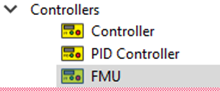
FMU
Description
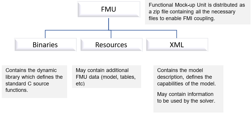
According to the Functional Mock-up Interface standard (https://fmi-standard.org), “The Functional Mock-up Interface is a free standard that defines a container and an interface to exchange dynamic simulation models using a combination of XML files, binaries and C code, distributed as a ZIP file. It is supported by 170+ tools and maintained as a Modelica Association Project.”
The Functional Mock-up Interface (FMI) is an open standard for the interface that facilitates model coupling between many simulation tools. It defines a ZIP archive and an application programming interface (API) to exchange dynamic models using a combination of XML files, binaries, and C code: the Functional Mock-up Unit (FMU).
Co-Simulation and Model Exchange
- Co-Simulation
-
- Coupling of simulation tools.
- Coupling of subsystem models, exported by a modeling environment, together with their solvers, as runnable code.
Figure 2. 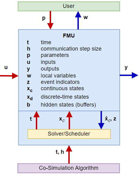
- Model Exchange
-
- Models are described by differential, algebraic, and discrete equations with time, state, and step events.
- Usually, an ODE/DAE solver.
Figure 3. 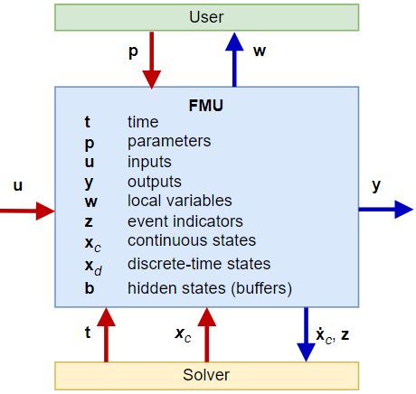
FMU in Flow Simulator
- Flow Simulator supports "exporting" an FMU. “Import” of an FMU is not supported.
- Only a co-simulation interface is supported.
- File-based coupling has been implemented.
- FMU supports both steady and transient cases.
- The FMU file structure in the ZIP file:
Figure 4. 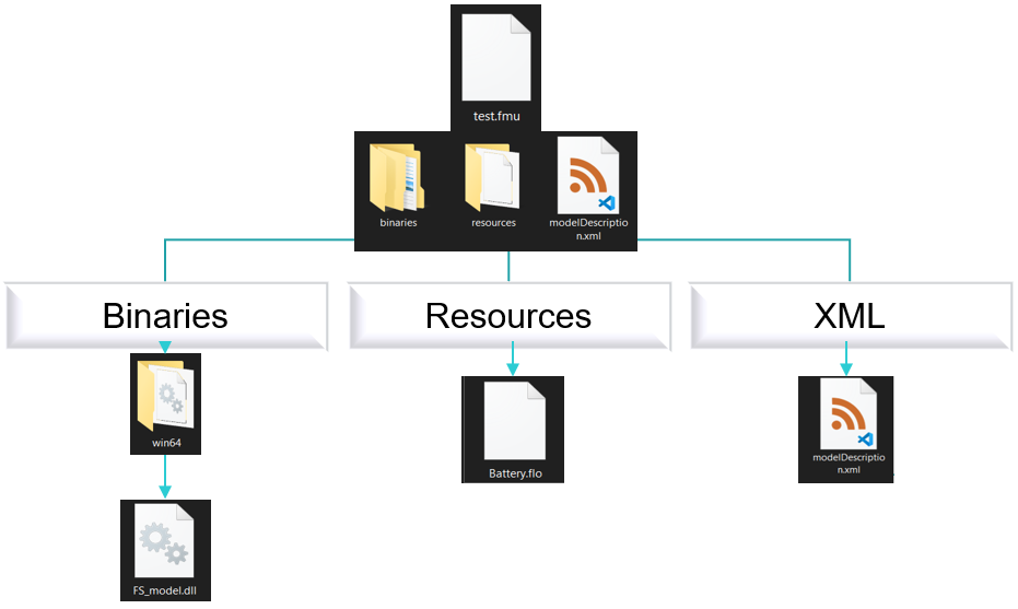
FMU Creation in the GUI
- Define Inputs and Outputs
- Defining input and output variables using the Define Inputs and Define
Outputs options are similar.
Figure 7. 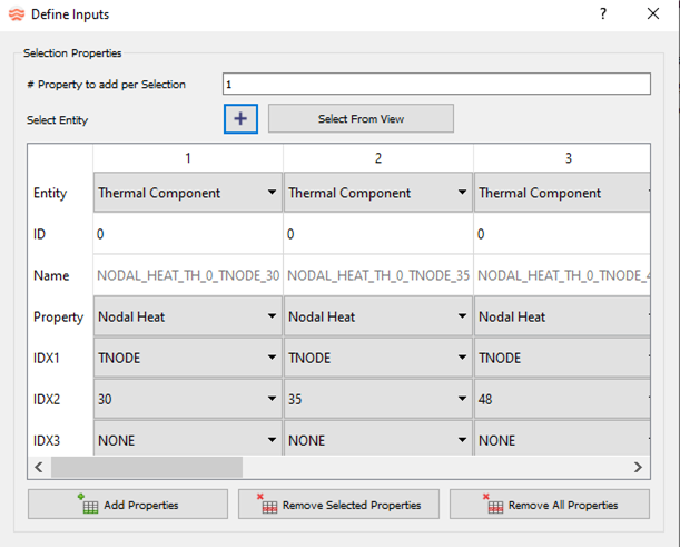
Use the Select Entity or Add Properties menu to add entities.- Click Select from View to select objects from the Flow Simulator model window. Select objects until the Select from View icon is clicked again, or the Define Inputs or Define Outputs window is closed.
- If you select Add Properties, empty Inputs or Outputs columns are created. Define each item.
- If you select Select Entity, then the
Object Selection window is
displayed. From here, enter the object ID in the
Selection Range section.
- You can select more than one object. Use “,” to select the item ID, or use “-“ to define a range.
- Objects are selected based on the selected Object Type.
Figure 8. 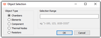
Gauge and manipulated variables contain the following fields:- Entity
- Chamber, Element, Component, and Thermal Component.
- ID
- The ID of the object for flow objects, or thermal network ID for thermal components.
- Name
- The Input/Output Variable name. When using Select from View, the name depends on the “Entity” selected. The naming convention is:
- Property
- Input or Output property of the object.
- IDX1
- Specific property types. For example, the station number for some Tube element properties, or Combination Flow Element flow fraction table row numbers, or the Thermal Component type: Tnode, Conductor, Convector, Radiator, or Heat Flow.
- IDX2
- Specific property types. For example, circumferential wall side ID for some Incompressible Tube properties, or the Thermal Component ID.
- IDX3
- Specific property types. For example, the left or right emissivity value of a two-surface radiator.
- Unit
- Selectable unit of each property, used to define inputs in the selected unit.
Additional options include Remove Selected Properties and Remove All Properties.
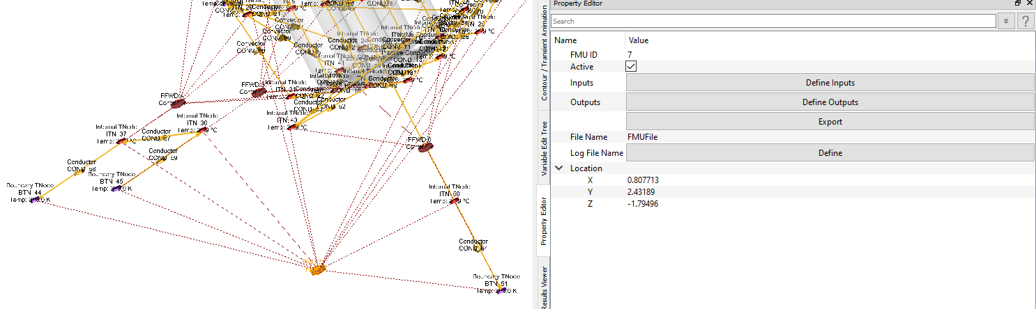
- Define File Names
- File Name Option: Name of the FMU. For example, in this case, once the FMU is created, it is named “FMUFile.fmu”. This name is different from the name of the Flow Simulator model.
- Exporting FMU
- Export Option: Once all the parameters are set, the Flow Simulator model needs to be saved before exporting. Export creates an FMU by the name provided in the "File Name".
- Zipping FMU (if the exported FMU is modified)
- If the exported FMU must be extracted and modified, you must zip it manually. The following specification for zipping must be followed:
- Special Note for Transient Cases
- While setting up a transient case for FMU creation, verify that
Initial Conditions Options in the
Run Control Parameters is set to
Steady State Solution at Start Time.
Figure 9. 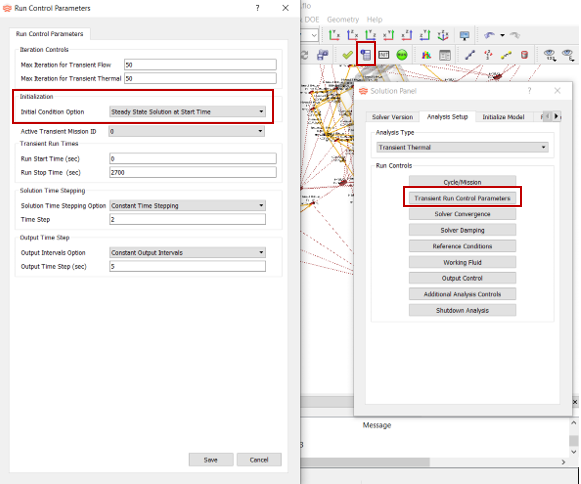
FMU .flo Entries
| Index | UI Name (.flo label) | Description |
|---|---|---|
| 1 | Type (CPTYPE) | Component Type. 5=Controller. |
| 2 | (SUBTYPE) | FMU = 6. |
| 3 | Active (ACTIVE) | Active or Inactive option for the FMU. |
| 4 | Debug (DEBUG) | Not used for FMU. |
| 5 | Relation Type 1 (RELATION1) | NONE: Always for FMU (Not used for FMU). |
| 6 | Relation Type 2 (RELATION2) | NONE: Always for FMU (Not used for FMU). |
| 7 | Name (VARNAME) | The Input/Output Variable name. When using Select
from View, the name is determined by the
Entity selected. The naming
convention is: name: {Property}_{Type(1st 2 chars)}_{id}_{idx1}_{idx2}. |
| 8 | (VARTYPE) | “GAUGE”: Input “MANIP”: Output |
| 9 | (ACT) | Active or Inactive option for the Input or Output variable. |
| 10 | Entity (ITEMTYPE) | Flow or thermal component that is defined as an input or
output variable in the FMU to be considered or affected during
the run time. Input and Output: “ELEMENT”, “CHAMBER”, “COMPONENT”, “THERMAL”. Output only: “MISSION”. |
| 11 | ID | Chamber/Element/Component ID or Thermal Network ID. |
| 12 | IDX1 | List of Flow Component specific properties. For example, the
station number for some properties of the Tube
element. Thermal Component type: Tnode, Conductor, Convector, Radiator, or Heat Flow. |
| 13 | IDX2 | List of Flow Component specific properties. For example,
circumferential wall side ID for some Incompressible Tube
properties. Thermal Component ID. |
| 14 | IDX3 | List of specific properties. For example, the left or right emissivity value of a two-surface radiator. |
| 15 | Property (PROPERTY) | Selected entity property that is counted (as GAUGE) or
altered (as MANIP) during the simulation. See the full list of available items in this file: <installation_directory>\Resources\misc_solver_files\controller_working_get_set.dat |
| 16 | Unit (UNIT_SET) | Selectable unit of each property, used to define inputs in the selected unit. |