Logic Tutorial
PollEx Logic is used to review the schematic design. Checking symbols and nets in sheets are possible.
-
Launch PollEx Logic and open a PollEx Logic Binary
file.
- Click PollExLogic from the PollEx Launcher.
- Click and open PollEx_Logic_Sample_r1.0.sdbb from C:\ProgramData\altair\PollEx\<version>\Examples.
-
Change Sheet Number.
-
Select sheet name 005 from the toolbar.
Figure 1. 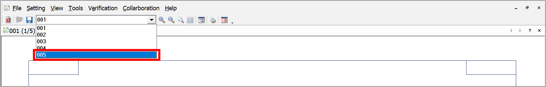
Figure 2. 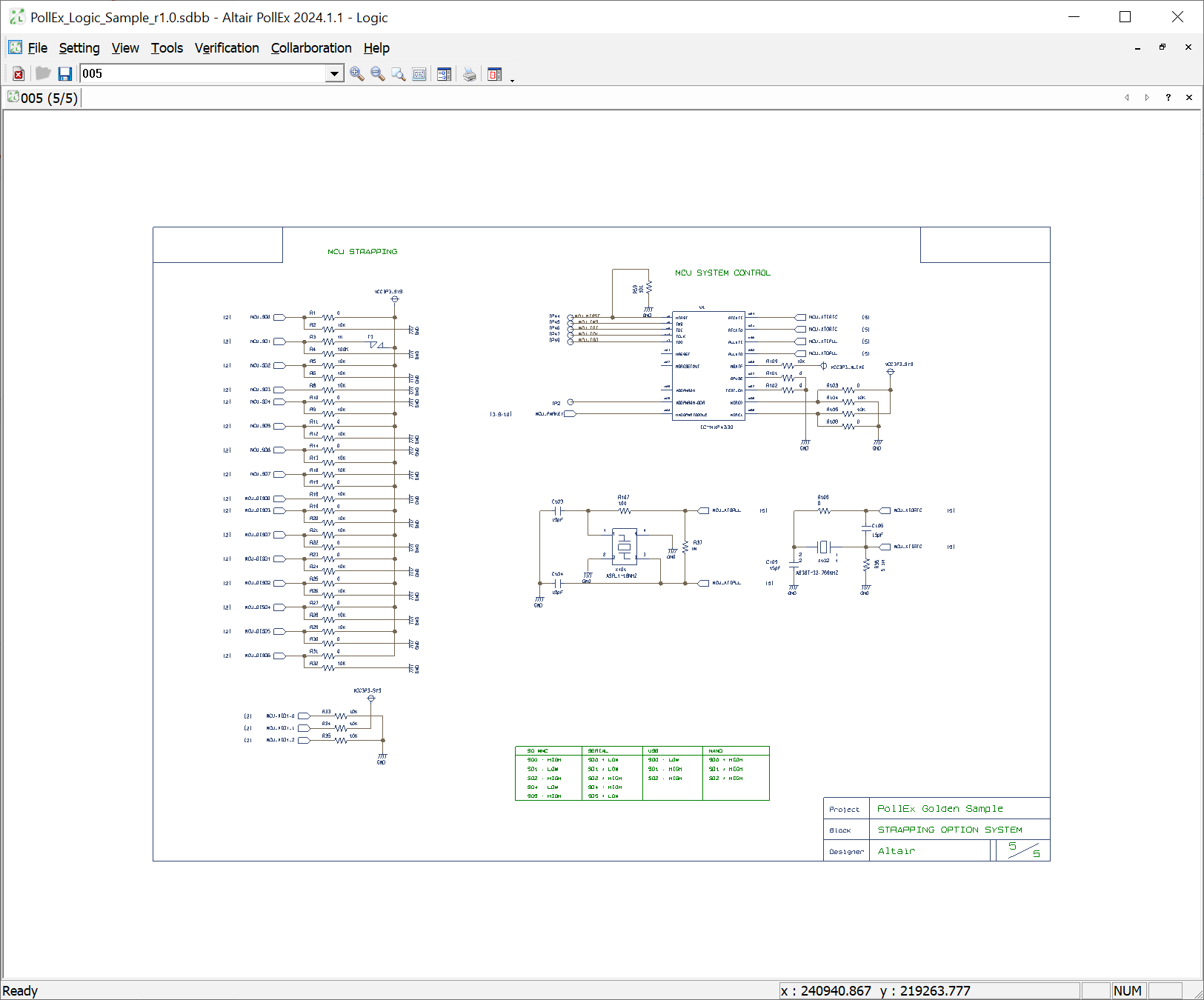
-
Select sheet name 005 from the toolbar.
-
Zoom Window.
-
Select the desired rectangle area as shown in the following
image:.
Figure 3. 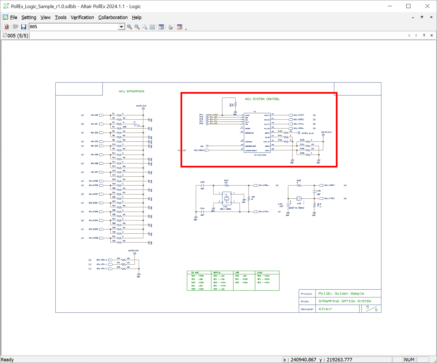
Figure 4. 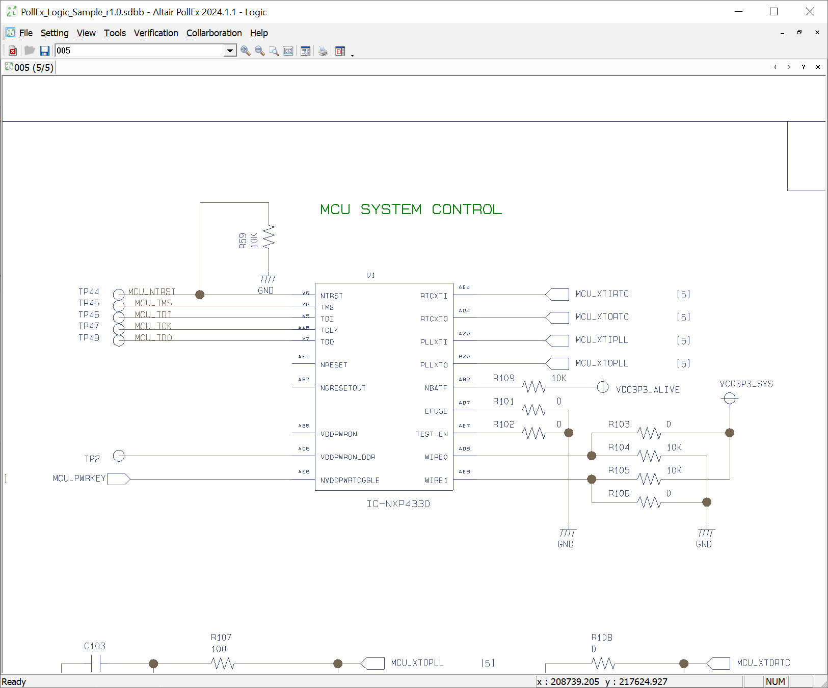
-
Select the desired rectangle area as shown in the following
image:.
-
Query for Symbol.
-
Click Property.
Figure 5. 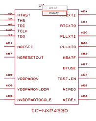
-
Click the Symbol tab in the
Property dialog to check the properties of part
and symbol.
Figure 6. 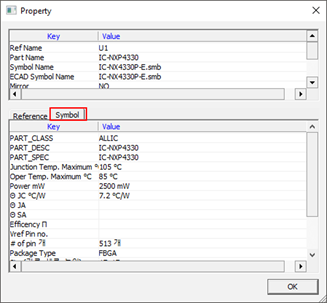
-
Click Property.
-
Query for Net Information.
-
Click Property.
Figure 7. 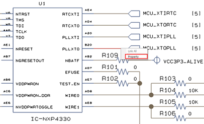
-
Click Property.
-
Search (Explorer) Object.
-
From the menu bar, click .
Figure 8. 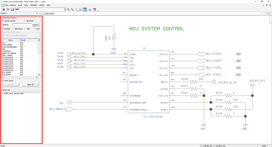
-
Select All Sheet in the Explorer pane and
double-click RC1005J101CS.
Figure 9. 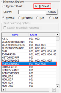
Figure 10. 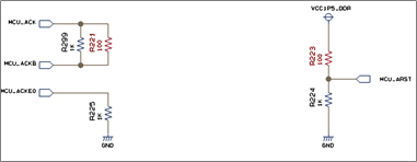
-
Double-click U204 from the list.
Figure 11. 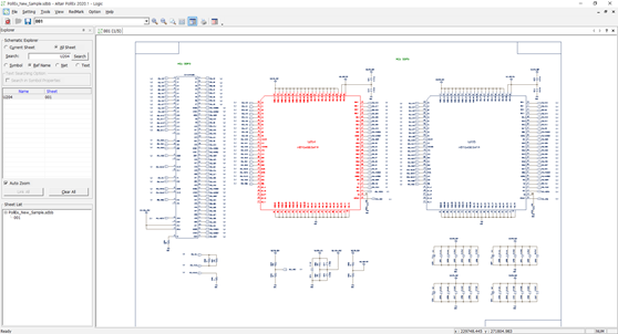
-
Double-click MCU_HDMI_TX0P from the list.
Figure 12. 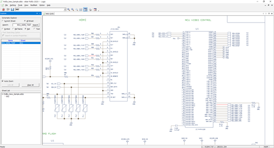
-
From the menu bar, click .
-
Symbol Viewer.
-
From the menu bar, click .
Figure 13. 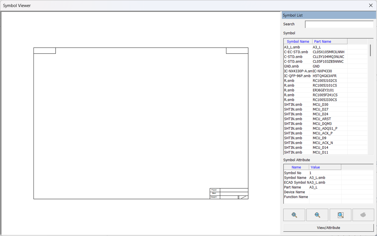
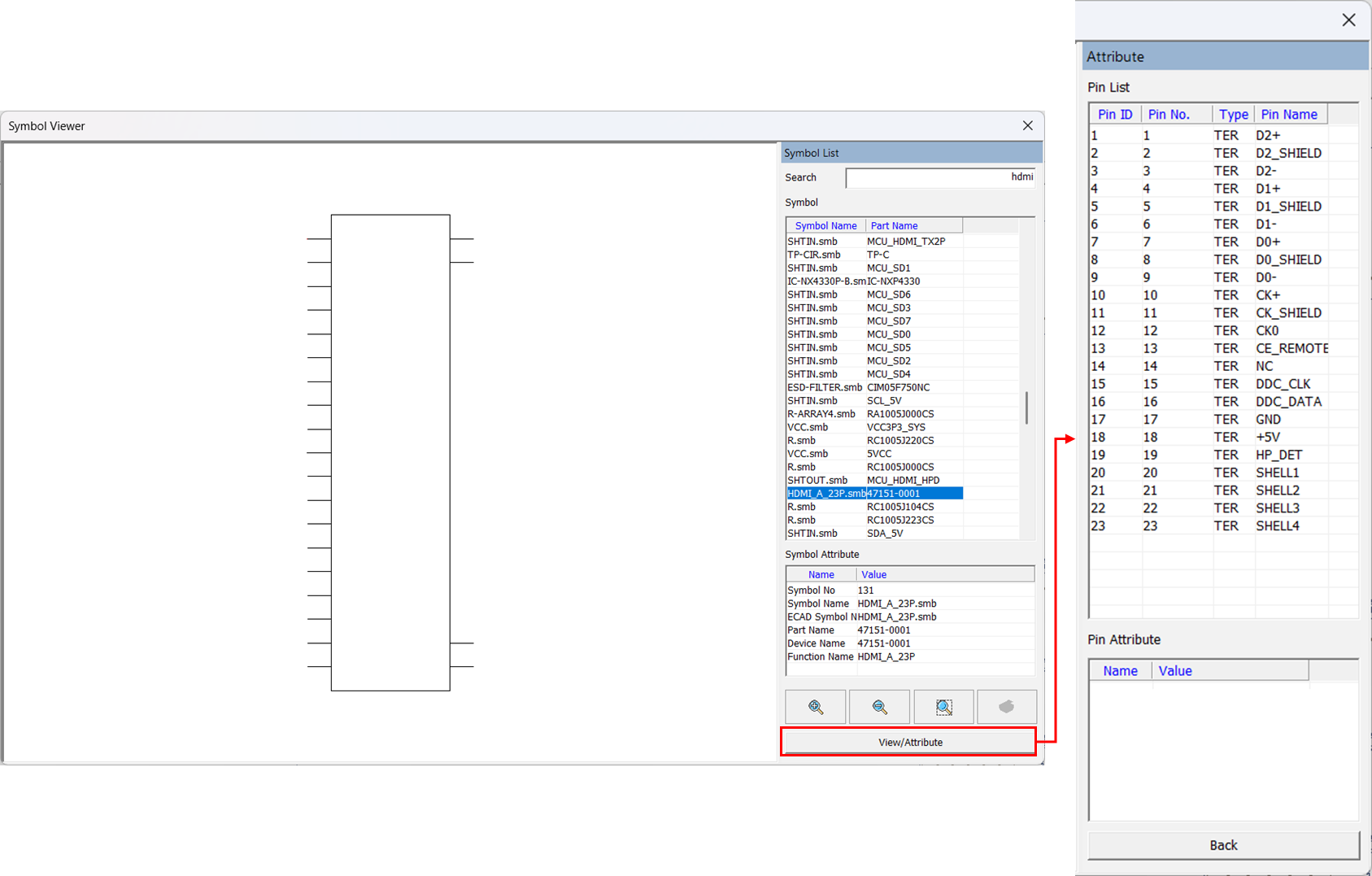
-
Click View/Attribute to check the part pin
information.
-
From the menu bar, click .
-
Extract Schematic Data.
-
Click Make List.
Figure 14. 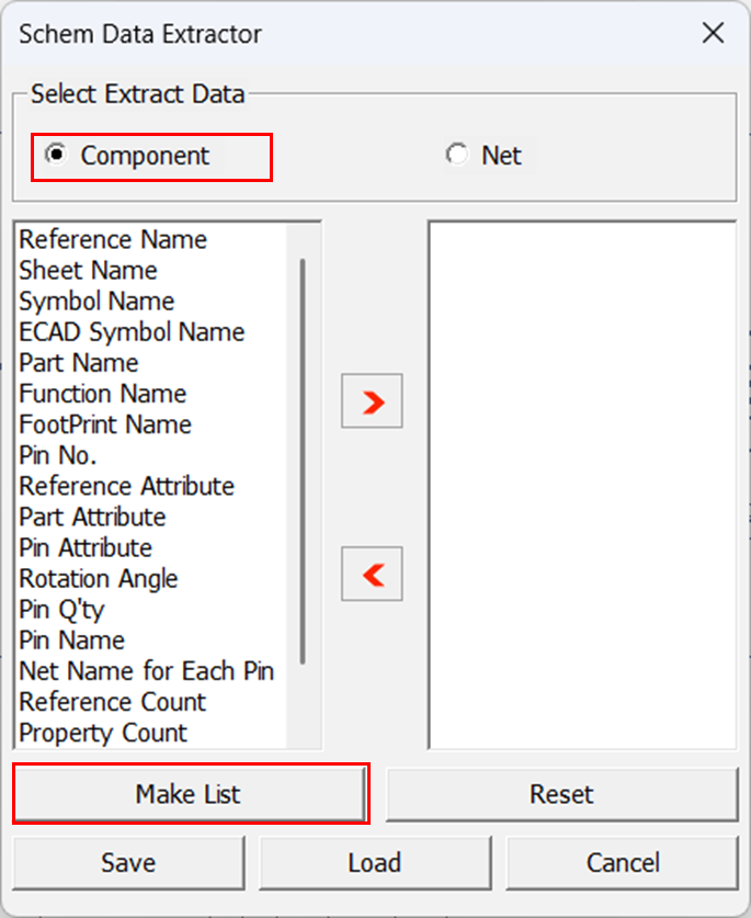
-
Click Export MS Excel.
Figure 15. 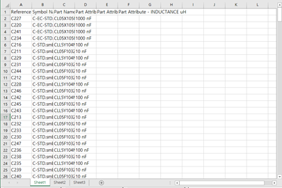
-
Click Make List.
-
Change Net Name.
-
Click OK.
Figure 16. Net Name Replacement 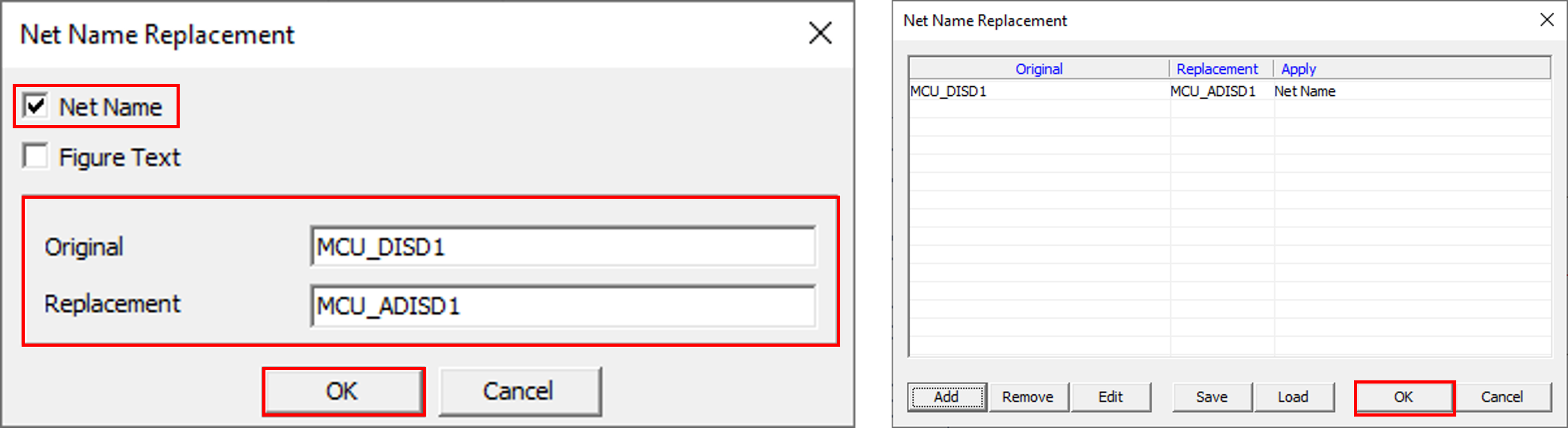
Note: Replaced Name is applied in the schematic design, but text of the net name is not changed. -
Click OK.