Make Board Paneling Tutorial
Make Board Paneling is a function to modify the data designed with a single sub board into an array type to use manufacturing related features such as Metal Mask Manager, Mounting Emulator, Block JIG Generator, Router-Machine JIG Generator, and so on.
Make Board Paneling using PDBB
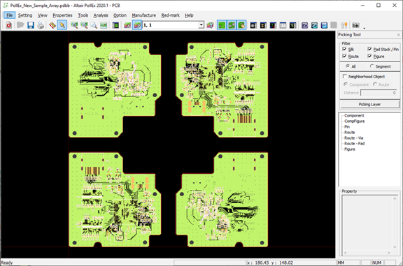
- Launch PollEx PCB.
- From the menu bar, click and open the PollEx_PCB_Sample_r<revision number>.pdbb file from C:\ProgramData\altair\PollEx\<version>\Examples.
- From the menu bar, click to open the Make Board Paneling dialog.
-
Create array.
- In the Make Board Paneling dialog, enable the Route checkbox.
- Enable the Board Figure checkbox.
- Enable the Board Outline checkbox.
- Click Add Board four times to register a total of four lists in Placement.
Note: A total of four lists, from No.1 to No.4, are created in Placement. -
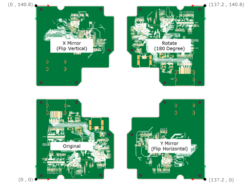
Set Array Placement No2.
- Select Y Mirror.
- Under Placement, enter 137.2 for dX and 0 for dY.
-
Set Array Placement No3.
- Select X Mirror.
- Under Placement, enter 0 for dX and 140.8 for dY.
-
Set Array Placement No4.
- For Rotation Angle, enter 180.
- Under Placement, enter 137.2 for dX and 140.8 for dY.
- Click Apply.
Note: The original data is copied and arranged as registered in the Array list..jpg)
-
Create Array.
- Select Column Spacing and Row Spacing under Array, then enter 10.
- Enter 2 for Count.
- Click Apply.
-
Create Panel Outline.
-
Click OK to close the Make Board
Paneling dialog.
Figure 1. Make Board Paneling dialog 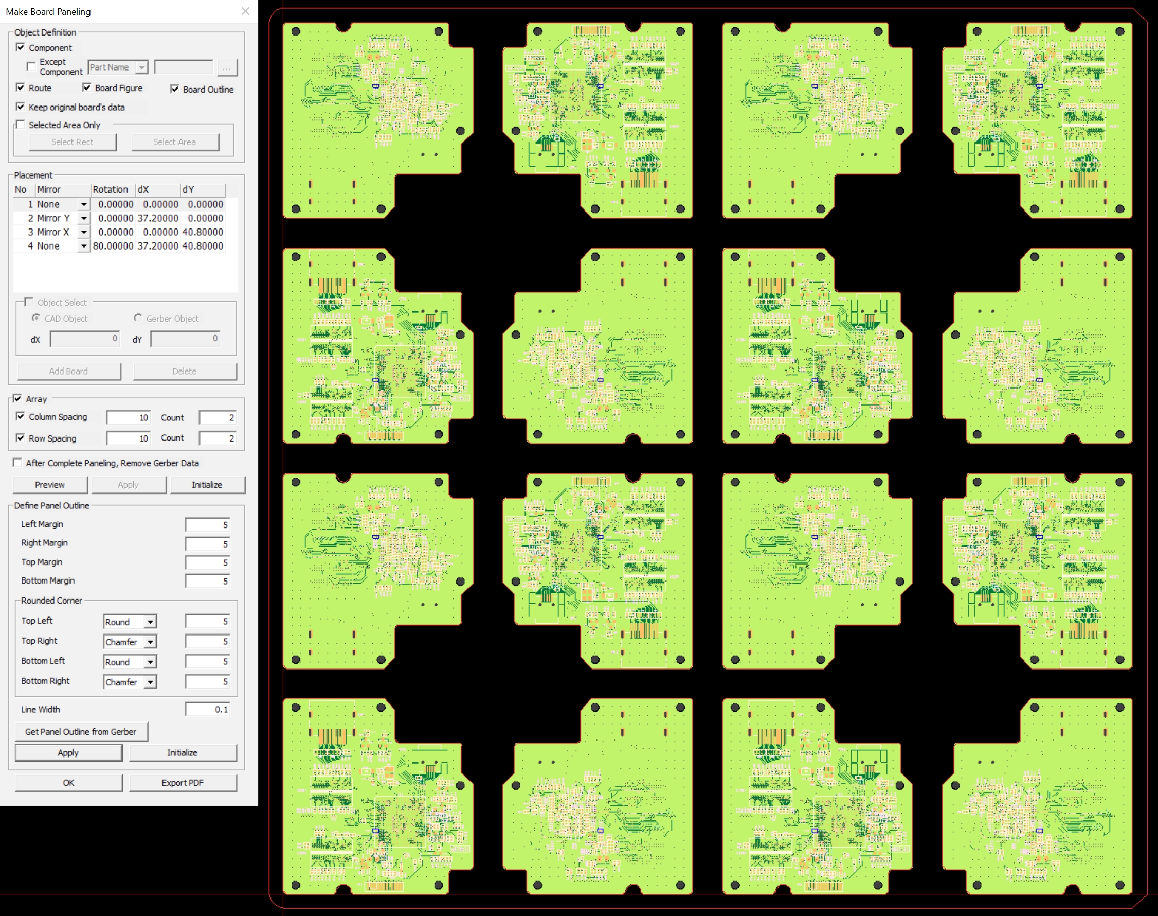
-
Click OK to close the Make Board
Paneling dialog.
Make Board Paneling using Gerber Data
- Launch PollEx PCB.
- From the menu bar, click and open the PollEx_PCB_Sample_r<revision number>.pdbb file from C:\ProgramData\altair\PollEx\<version>\Examples.
-
Import Gerber data.
When the Metal Mask Gerber of the panel board is prepared, the sub-boards can be automatically calculated by selecting the component pad of the design data and the pad object of the Gerber data.
- From the menu bar, click . to open the Import from Gerber (RS-274D/RS-274X) dialog.
-
In the Import from Gerber (RS-274D/RS-274X)
dialog, click
 .
.
- Select all Top-Metal files from C:\ProgramData\altair\PollEx\<version>\Examples\MFG\Data\MetalMaskGerber.
-
From the tool bar, click
 to
disable routing data.
to
disable routing data.
- From the menu bar, click to open the Make Board Paneling dialog.
-
Create Array List by selecting CAD and Gerber data.
- In the Object Definition section of the Make Board Paneling dialog, enable the following checkboxes: Route, Board Figure, and Board Outline.
- In the Object Select checkbox and select CAD Object.
- Select the Pad to be used as the reference from the CAD data.
Figure 2. 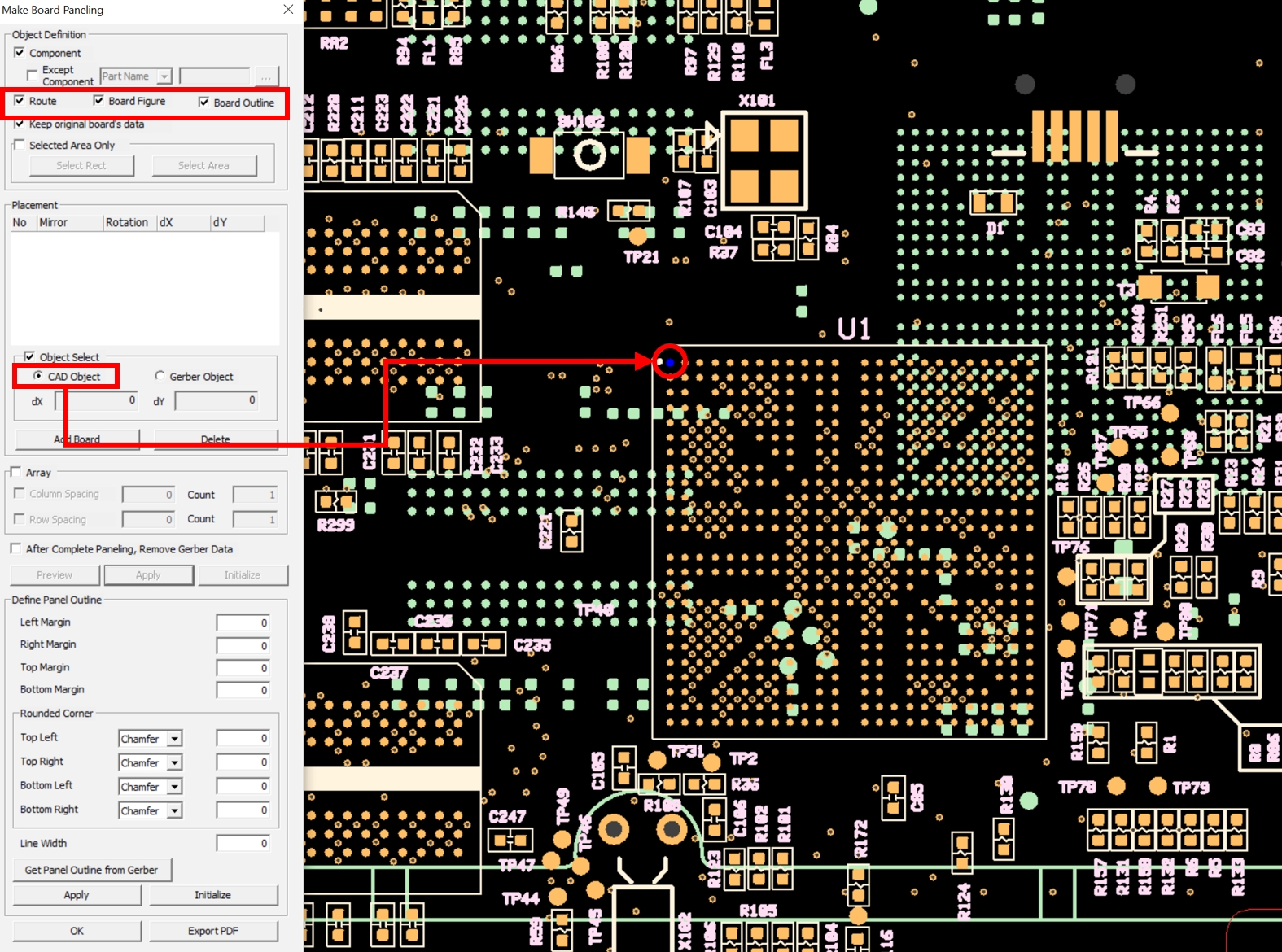
-
Select pad based on Gerber data.
-
Click Add Board.
Figure 3. 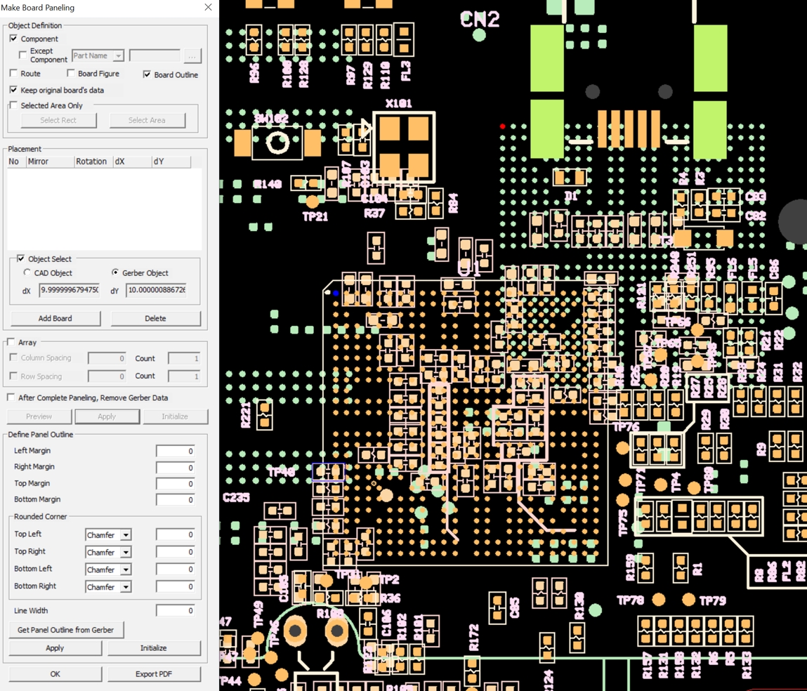
-
Click Apply.
Note: The original data is copied and arranged as registered in the Placement list.
Figure 4. 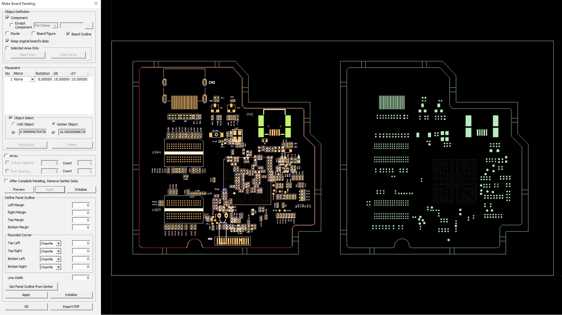
-
Click Add Board.
-
Create Panel outline.
Use the Get Panel Outline from Gerber option to define the Panel Outline.
-
Enable the Certain Width checkbox and enter
0.2.
Figure 5. 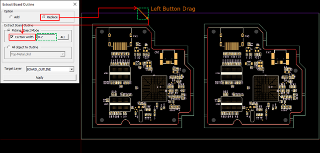
-
Click ALL.
All lines with the same width as the previously selected line are automatically selected and displayed in purple in the Gerber data.
Figure 6. 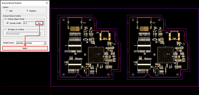
-
Click Close in the Make Board
Paneling dialog.
Figure 7. 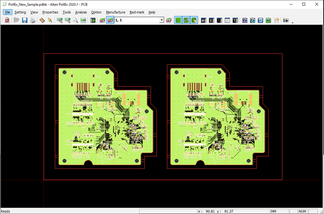
-
Enable the Certain Width checkbox and enter
0.2.
Make Board Paneling - Export PDF
- Launch PollEx PCB.
- From the menu bar, click and open the PollEx_PCB_Sample_r<revision number>.pdbb file from C:\ProgramData\altair\PollEx\<version>\Examples.
- From the menu bar, click .
-
Create Array.
-
Click Apply.
Figure 8. 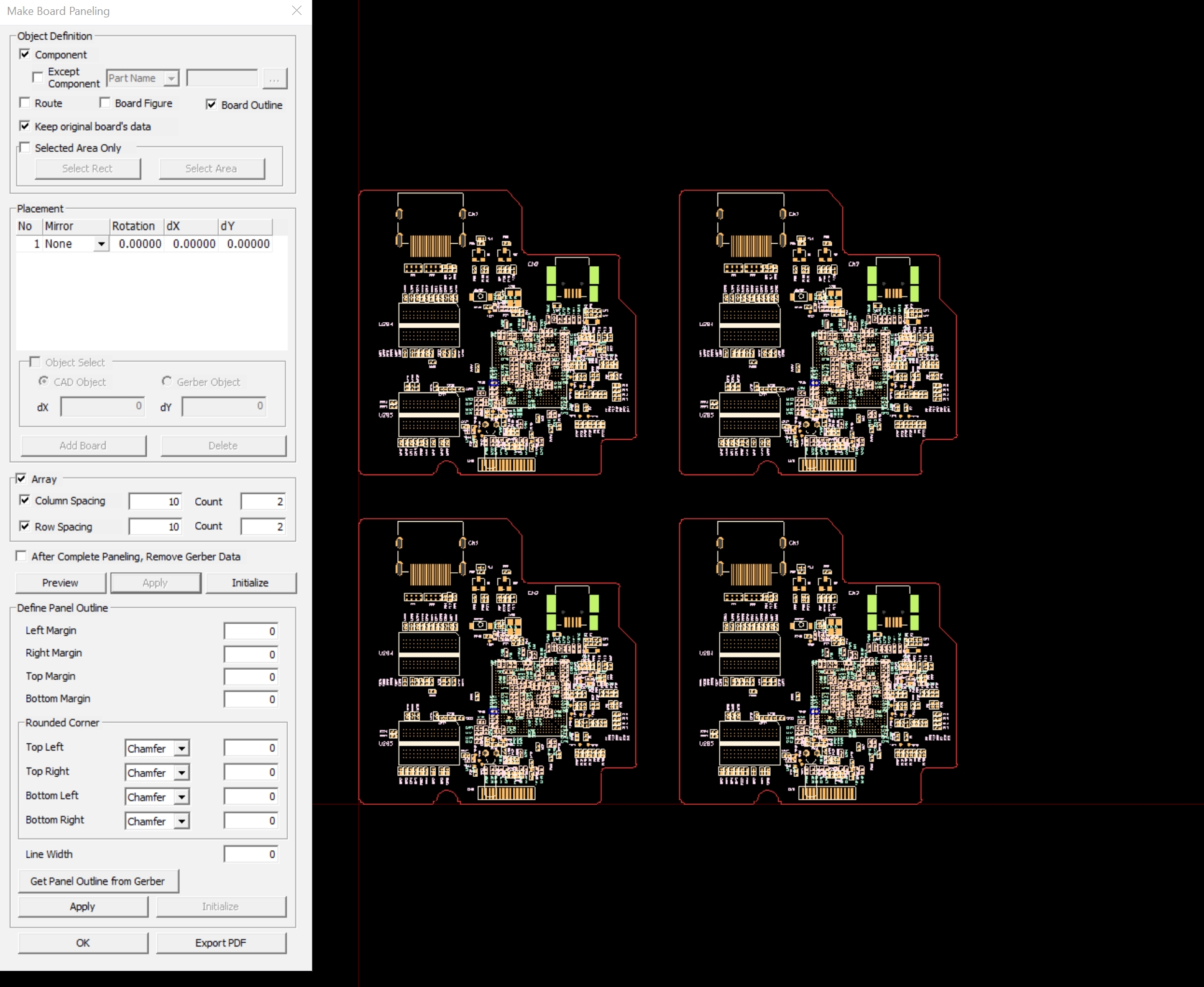
-
Click Apply.
-
Create Panel Outline.
In the Define Panel Outline section, you can define the Panel Board outline.
-
Create Rounded Corner.
- Set the Top Left and Right to Round and enter 5.
- Set the Bottom Left and Right to Chamfer and enter 5.
- Click Apply.
Figure 9. 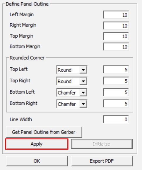
Figure 10. 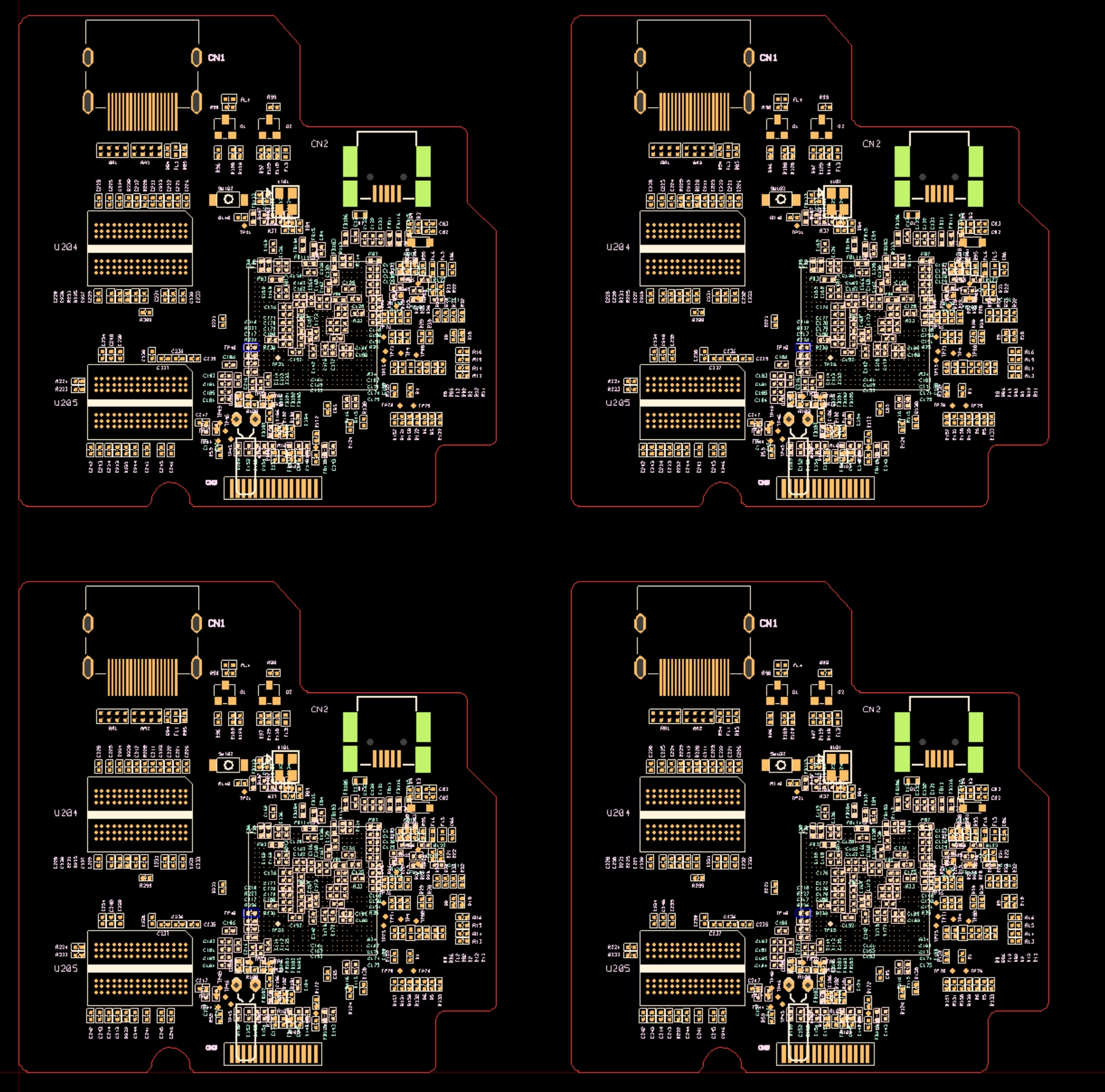
-
Create Rounded Corner.
-
Export PDF.
-
Click Add Page to create a new page. A list of
pages created is displayed in the top left.
Figure 11. 
-
Select the file SheetForm.dxf from
C:\ProgramData\altair\PollEx\<version>\Examples\MFG\MakeBoardPaneling.
Note: The sheet form is displayed on the screen.
Figure 12. 
-
Click Add Page to create a new page. A list of
pages created is displayed in the top left.
-
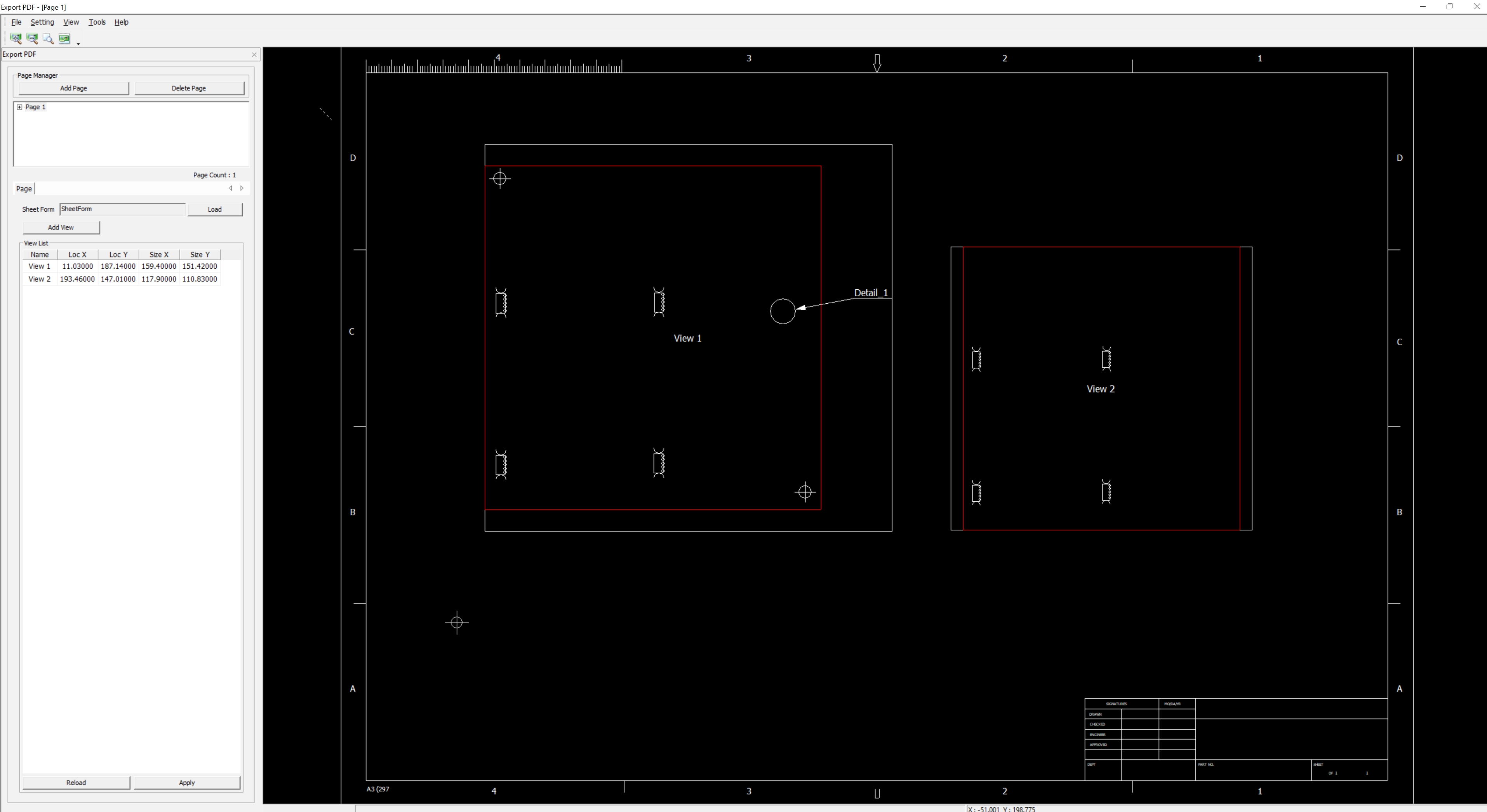
Add Paneling Board View.
-
Click and drag in the right screen to create a view area.
Figure 13. 
-
Click the created View in the Page Manager list. The PCB layout will be
displayed on the screen.
Figure 14. 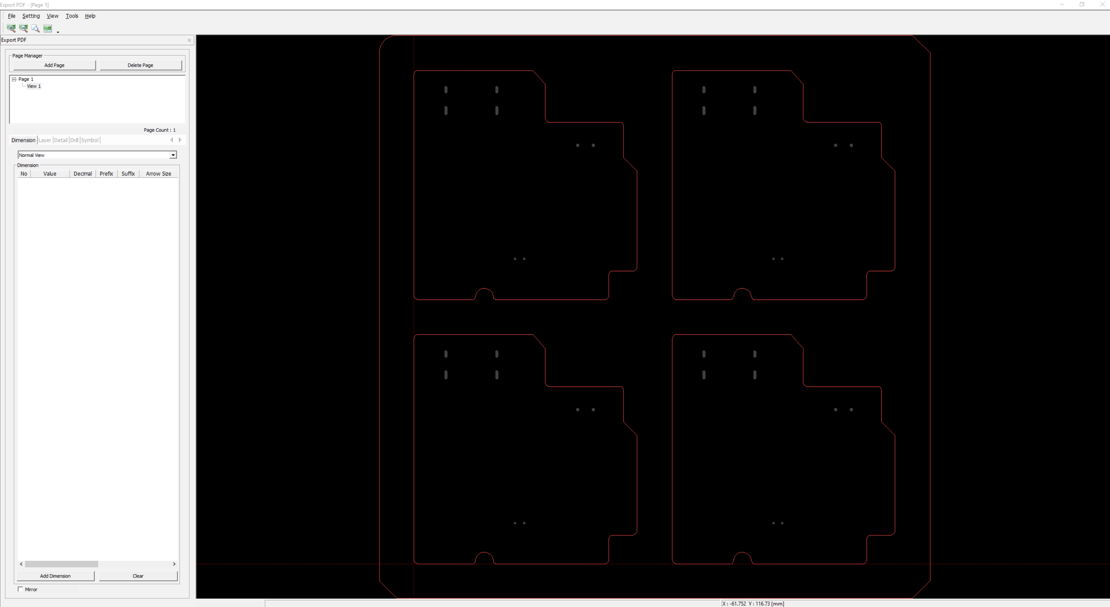 Note: If you check the Mirror option at the bottom, it displays the PCB layout in a mirrored state.
-
Click and drag in the right screen to create a view area.
-
Add Drill.
-
Right-click to adjust the size and set the rotation, then left-click at
the desired location to add the drill.
Figure 15. 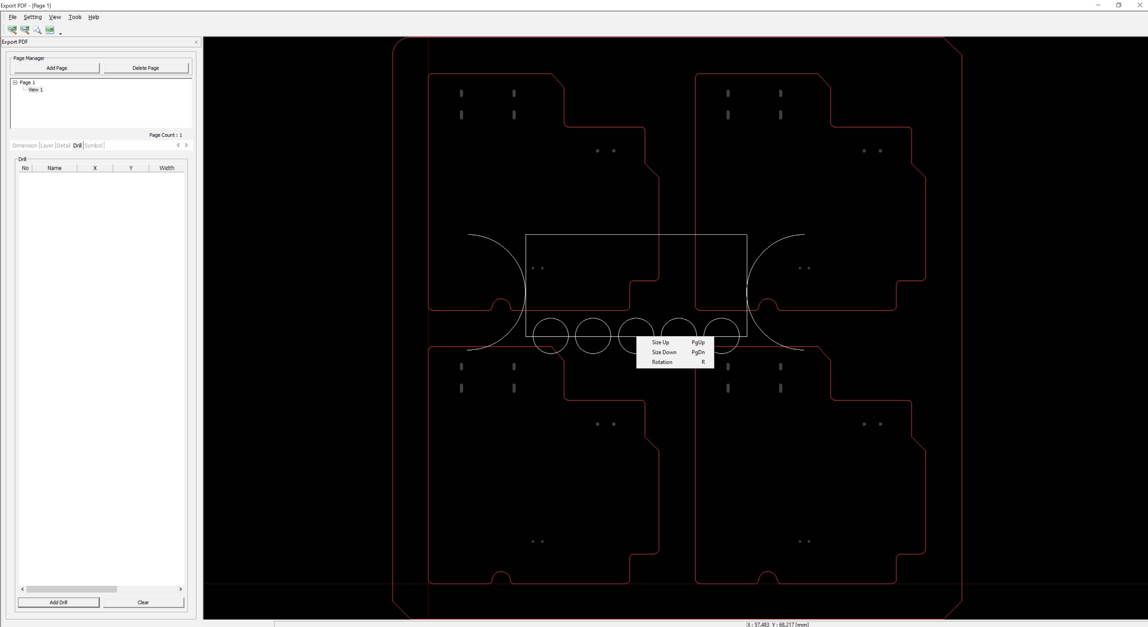
Figure 16. 
-
Right-click to adjust the size and set the rotation, then left-click at
the desired location to add the drill.
-
Add Symbol.
-
Right-click to adjust the size and set the rotation, then left-click at
the desired location to add the symbol.
Figure 17. 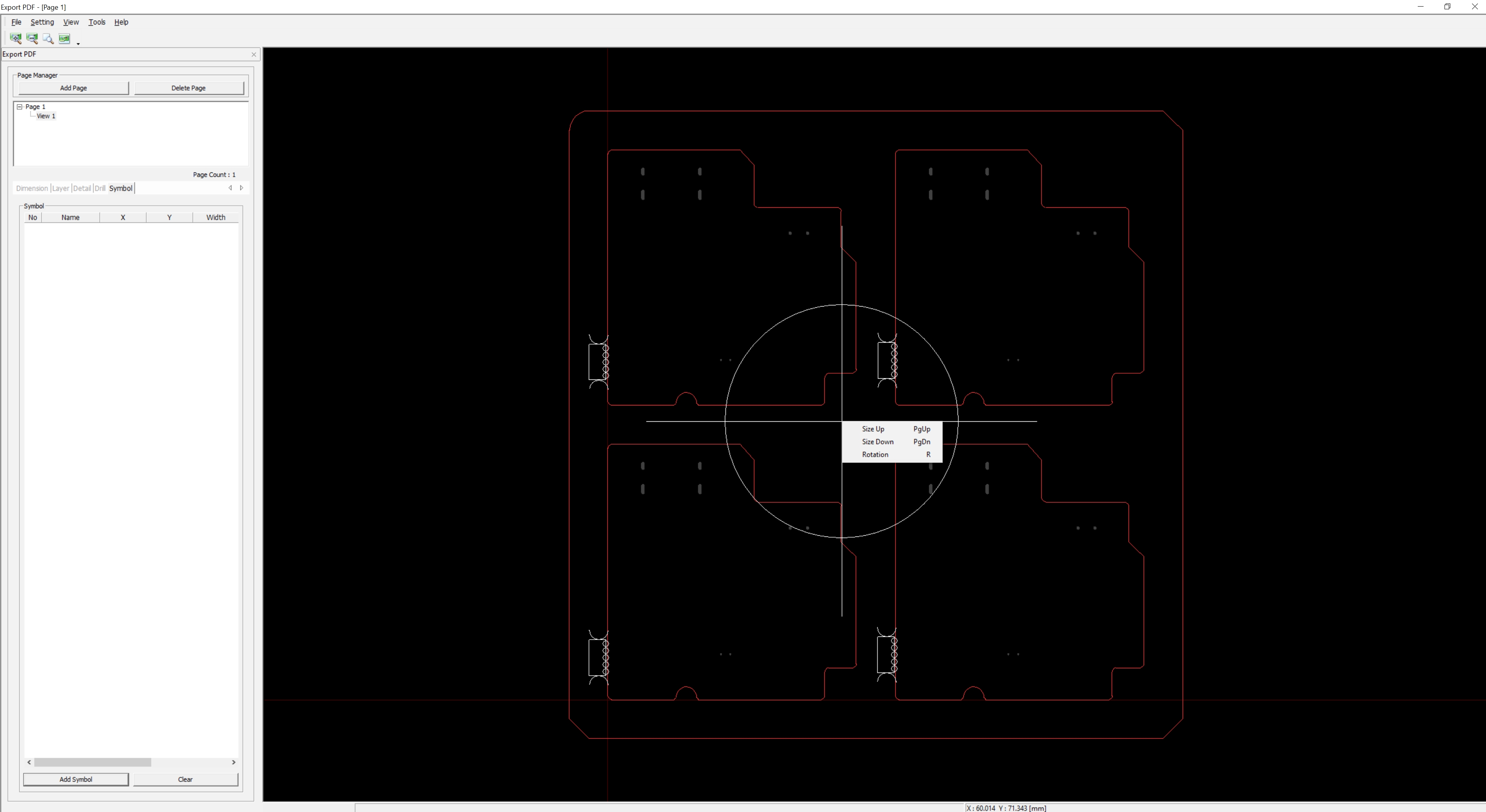
Figure 18. 
-
Right-click to adjust the size and set the rotation, then left-click at
the desired location to add the symbol.
-
Add Detail.
- In the Detail tab, click the Add
Detail.
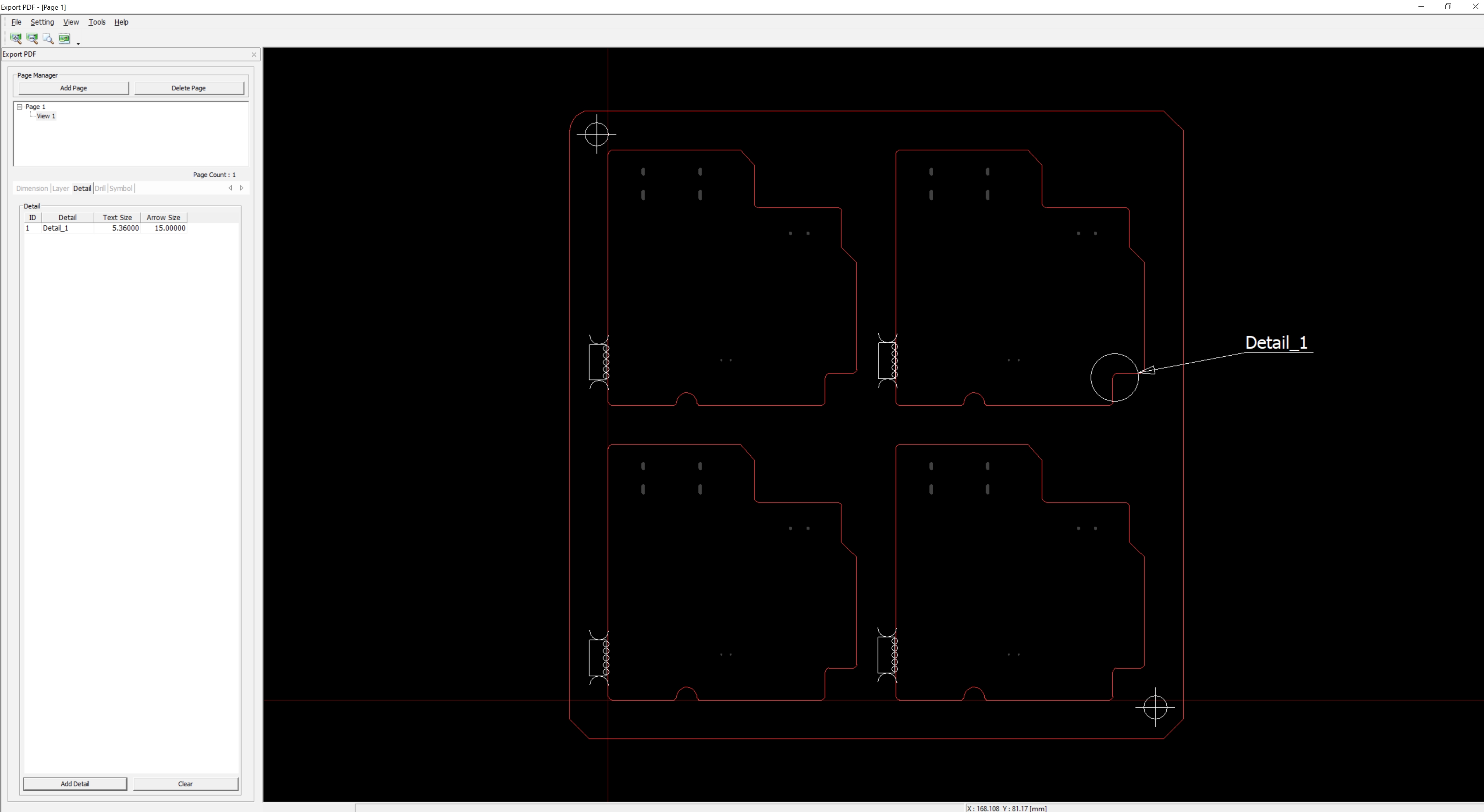
- In the Page tab, click the Add
View.
- In the View2, select in list.
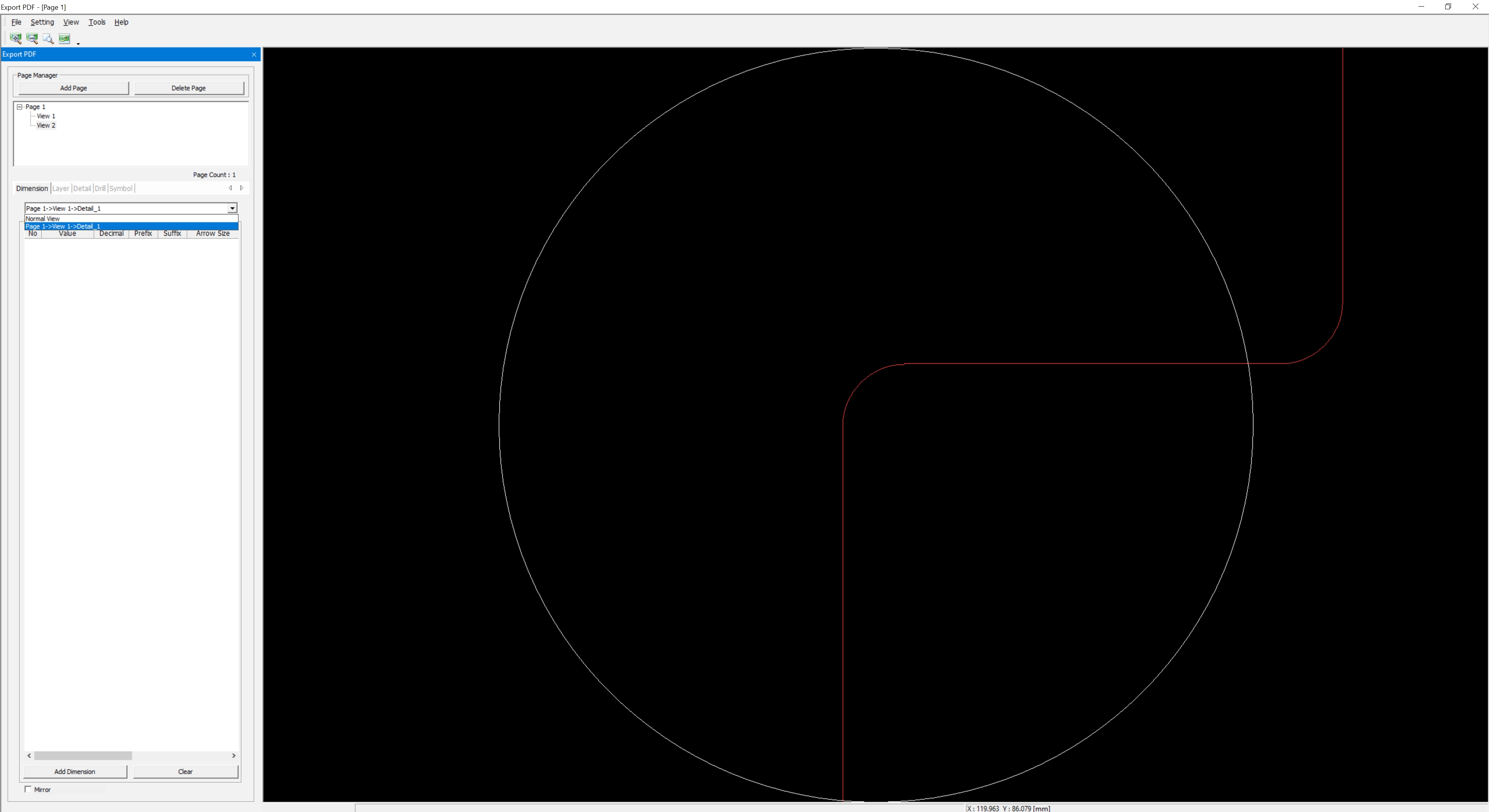
- In the Detail tab, click the Add
Detail.
-
Add Dimension.
-
Left-click to apply the measurement value to the screen.
Figure 19. 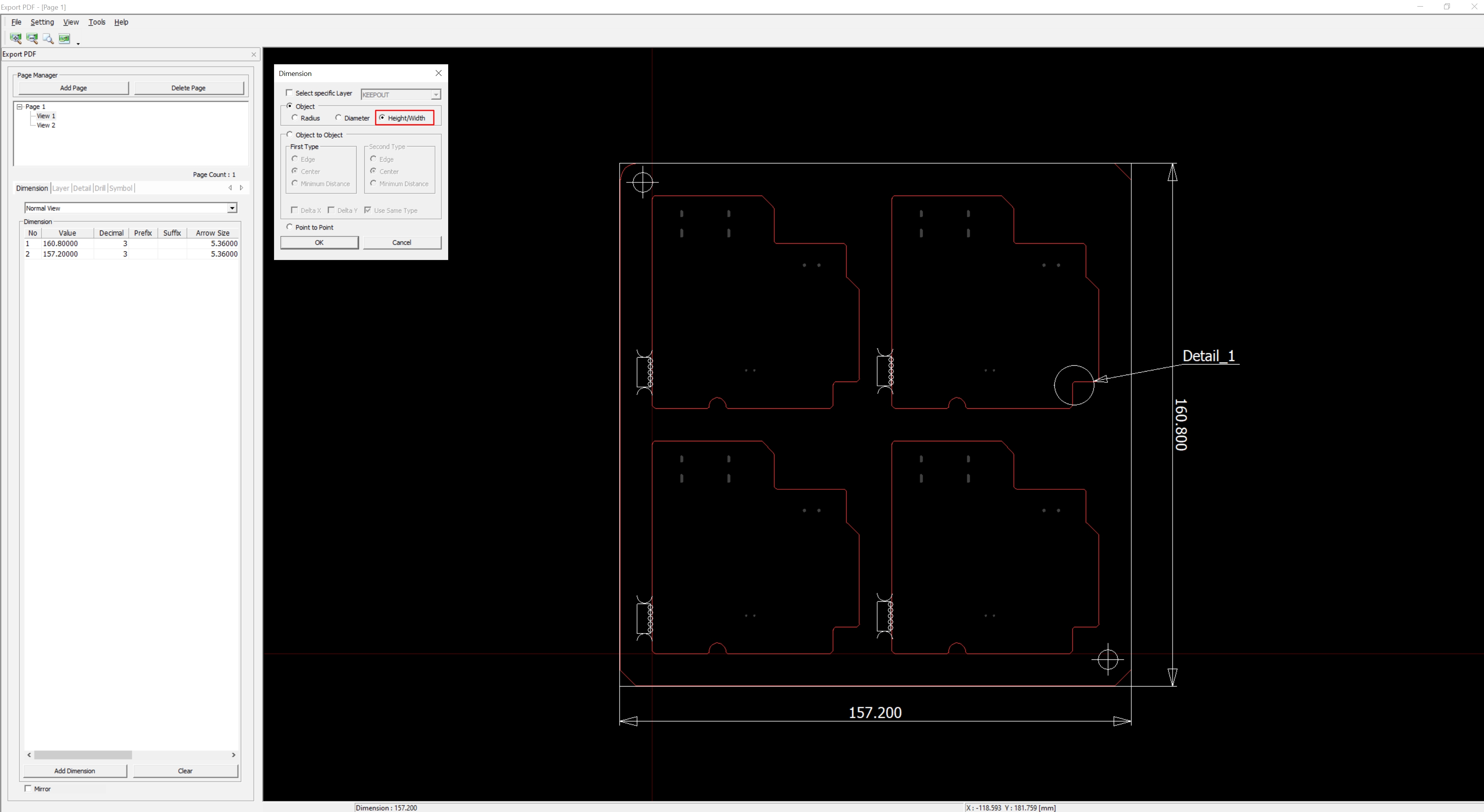
-
Left-click to apply the measurement value.
Figure 20. 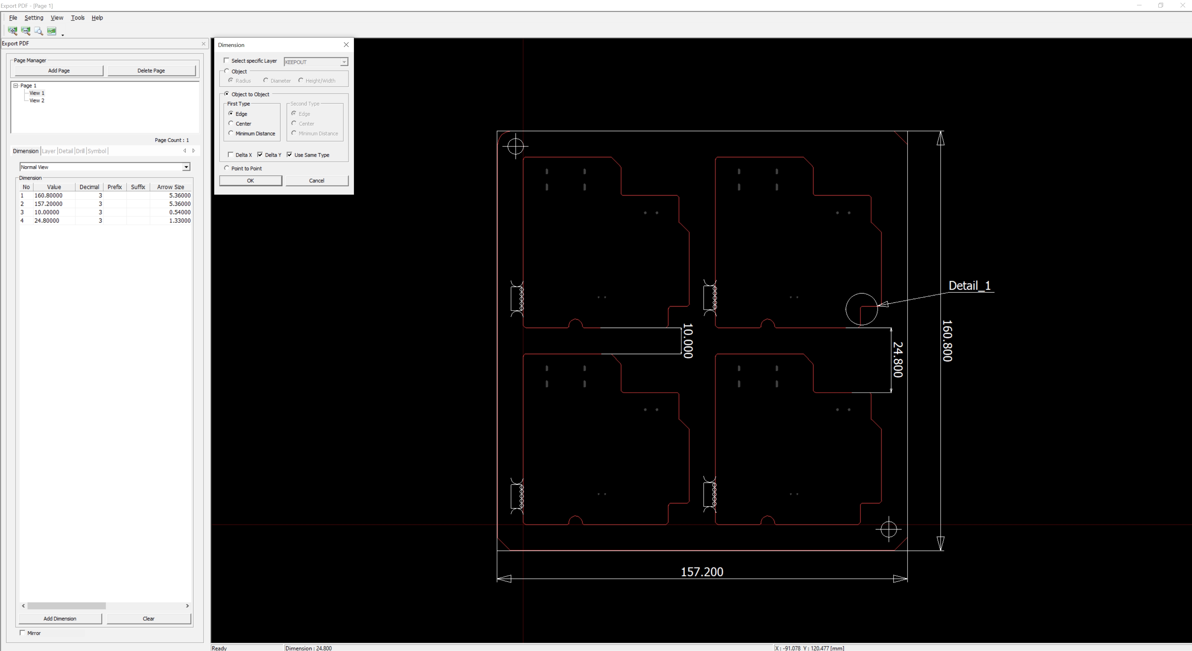
-
Left-click to apply the measurement value to the screen.
-
Layer Settings.
-
In the Layer tab, select the MECHANICAL14-TOP in
the View area (Multiple selections are allowed).
The layer is displayed on the screen.
Figure 21. 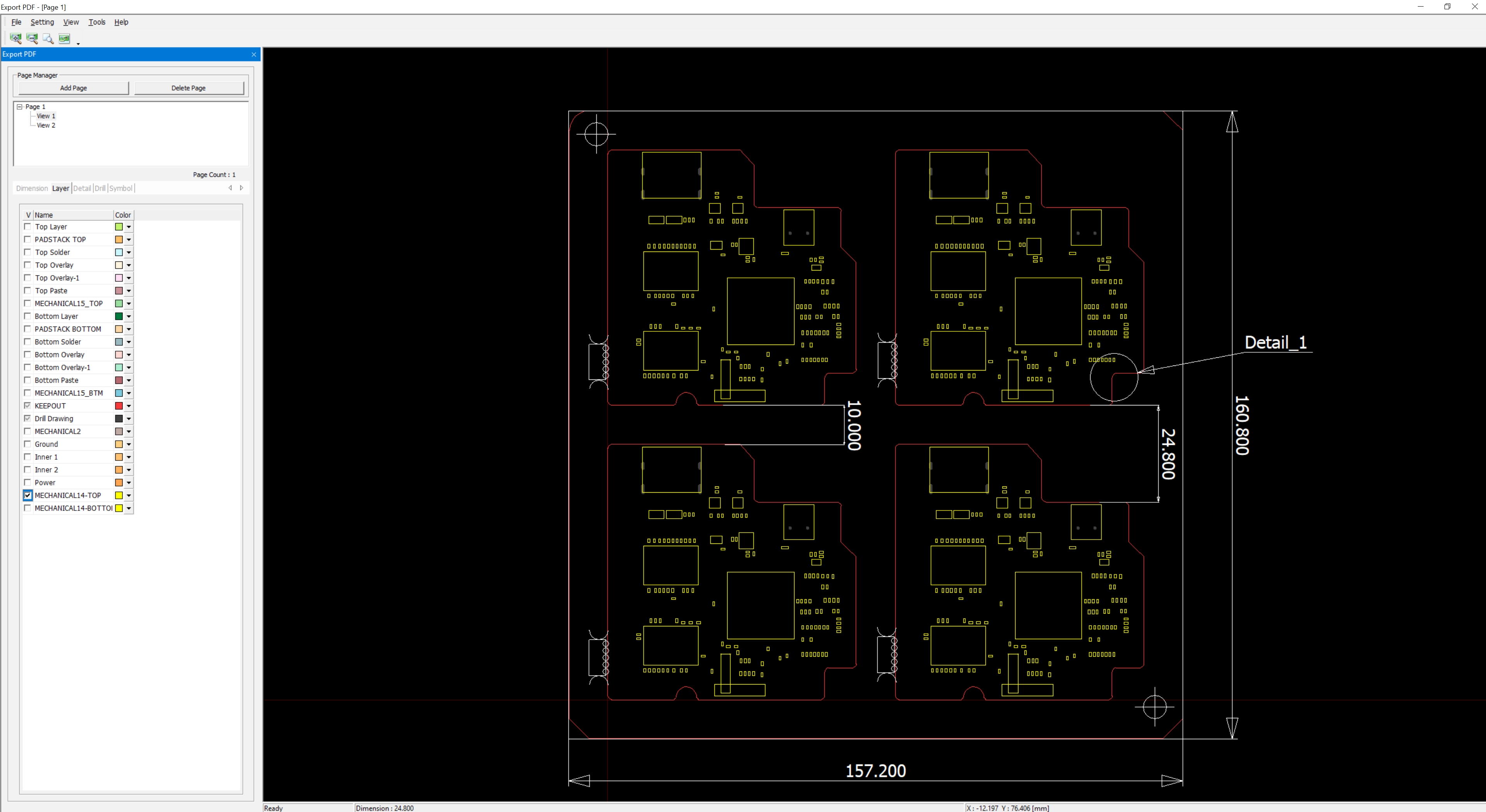
-
In the Layer tab, select the MECHANICAL14-TOP in
the View area (Multiple selections are allowed).
-
Save and Export PDF.
-
Save the created data as a *.ppd file.
Figure 22. 
-
Click to output the PDF file.
Figure 23. 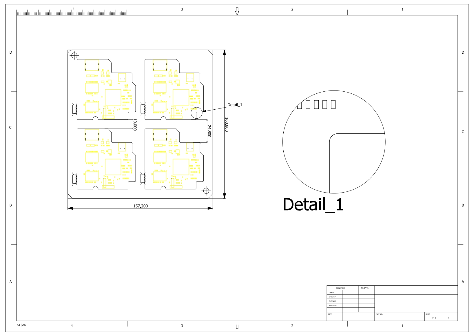
-
Save the created data as a *.ppd file.
-
Save and Export DXF
- Save the created data as a *.dxf file.
Figure 24. 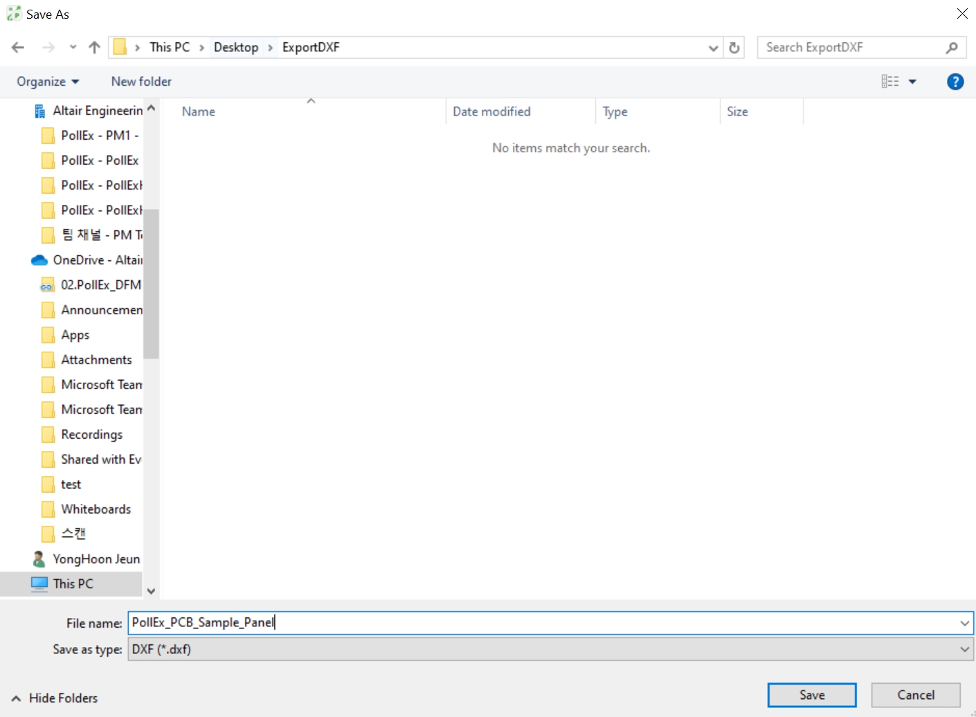
- Drag .dxf file on OpenCAD
Figure 25. 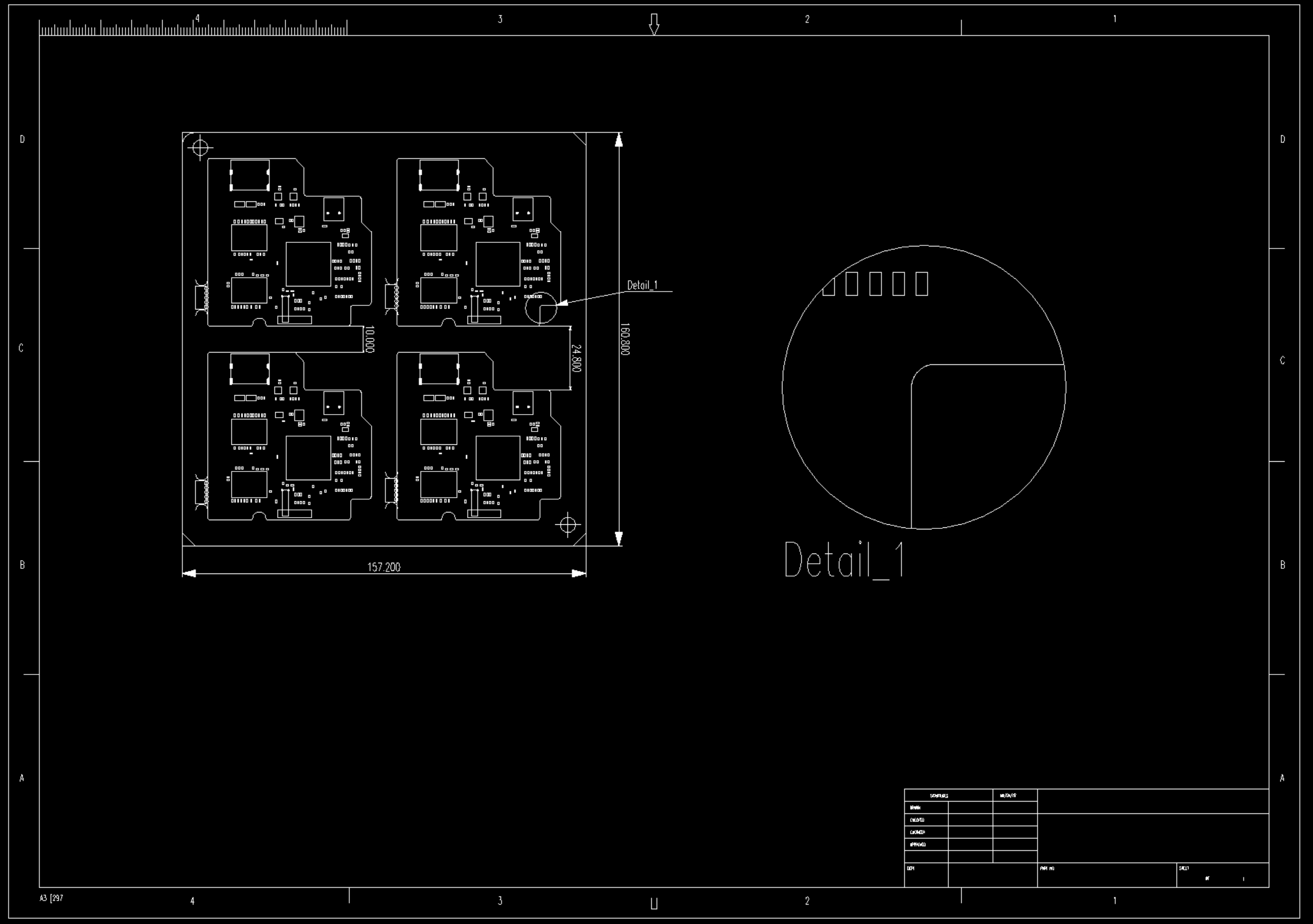
- Save the created data as a *.dxf file.