Impedance
This item analyzes and checks single-ended and differential impedance of target nets.
This item checks the followings:
- Check the single-ended impedance.
- Check the differential impedance (Characteristic, Zdiff,
Zcommon).
Figure 1. 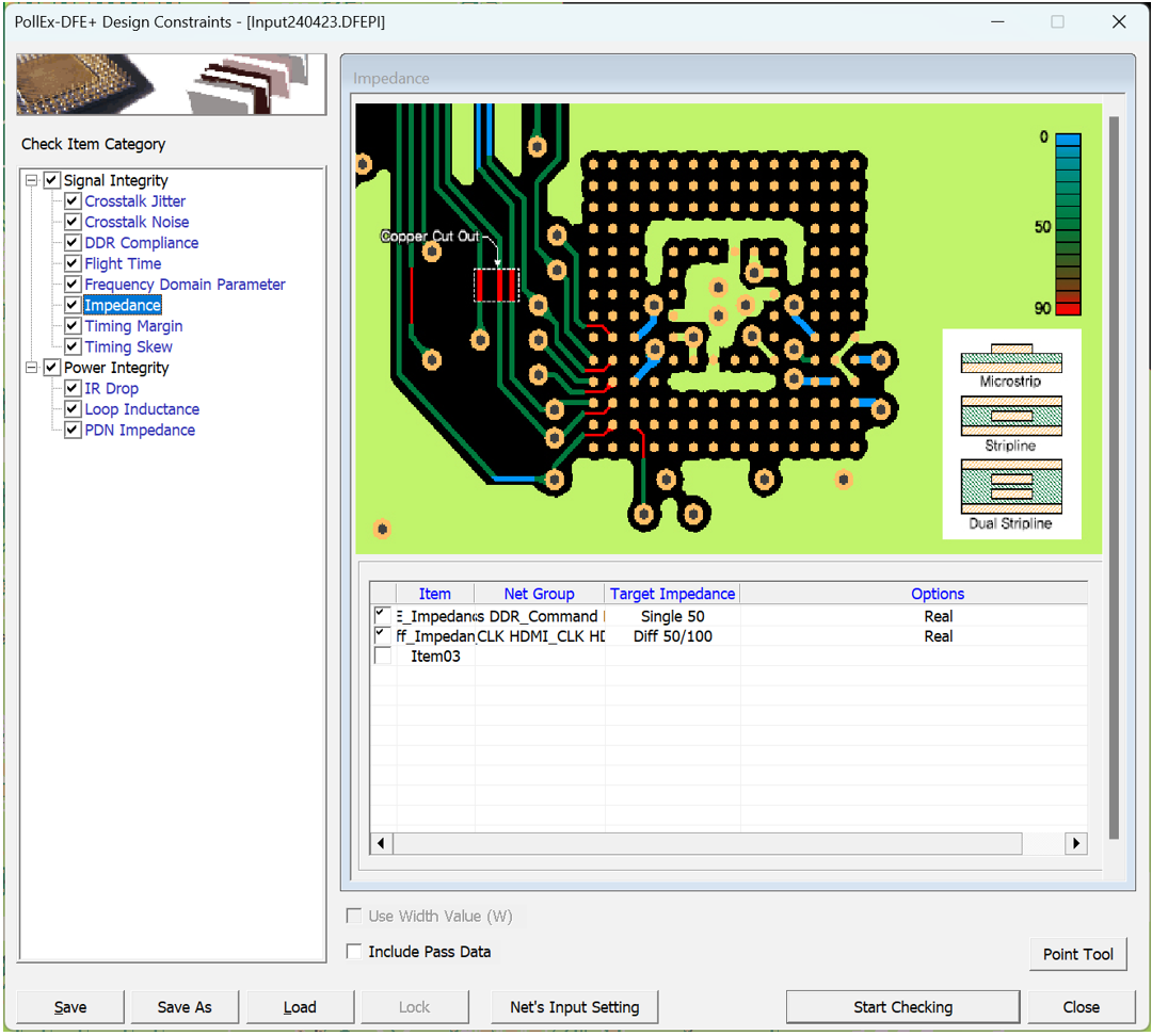
- Item: Enter sub item name. User can enter arbitrary name.
- Net Group: Select target net groups to be tested. Allow multiple net groups.
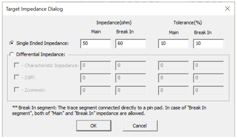
- Target Impedance: You can assign required impedance for main area and break
in area. You can also set tolerance (%) for each main area and break in
area.
Figure 2.
- Options: You can assign PIN/VIA Escape length and other options.
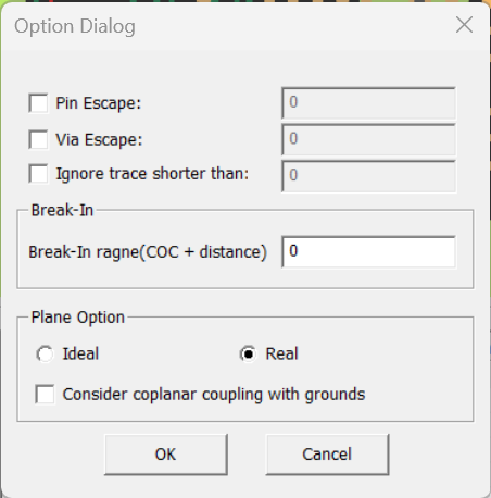
- Pin Escape: Enter a radius of circular region around pins to be excluded for the rule check.
- Via Escape: Enter a radius of circular region around vias to be excluded for the rule check.
- Ignore trace shorter than: the trace shorter than this length will be ignored.
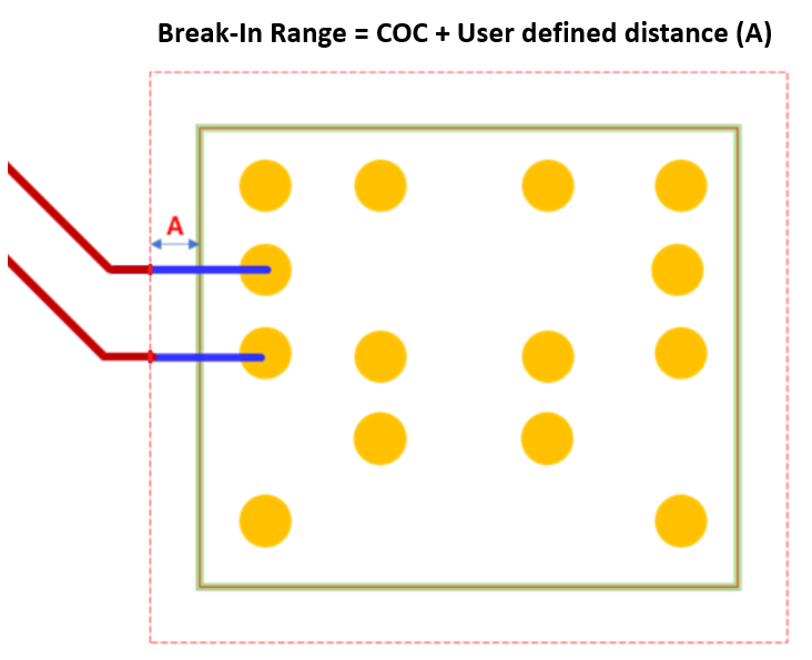
- Break-In range (COC+distance): Enter Break-In range value. The break-in
range refers to the sum of the distance within the COC line and the user
defined distance outside of COC line.
Figure 3.
- Ideal: Consider the reference plane as ideal plane during analysis. If this option is used, the reference is determined using the settings of the PCB stackup.
- Real: Analysis proceed by reflecting the shape of the reference plane. If this option is used, the net with net type "Ground" is regarded as the reference plane.
- Consider coplanar coupling with grounds: By checking this option, the analysis will consider the coupling effect of the coplanar ground.
Impedance Result
- Result dialog:
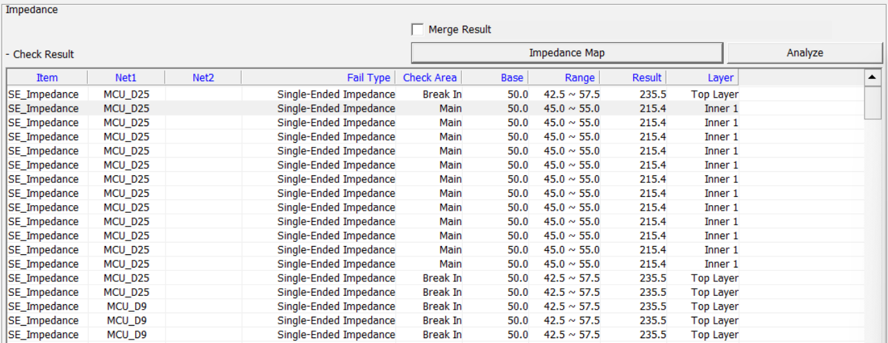
- Merge Result: Results are displayed sorted by Net and Layer for easy reference.
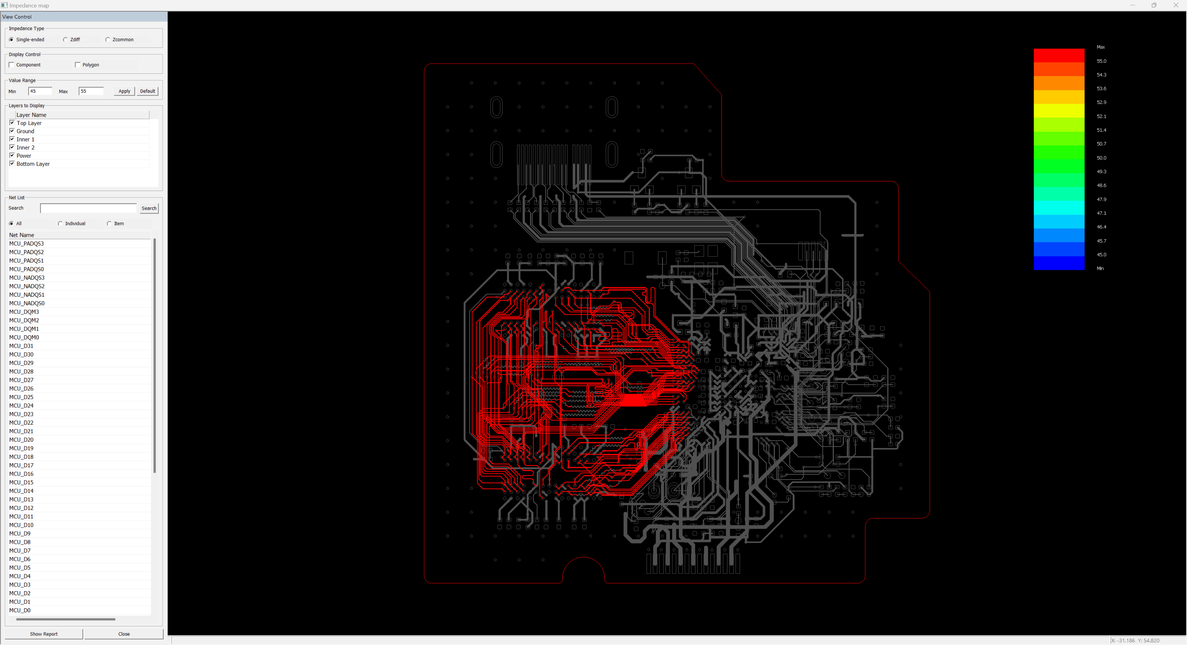
- Impedance Map: Display impedance map on the design.
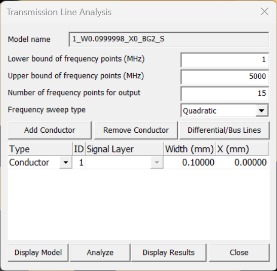
- Analyze: In the Impedance results list, select the desired result item, then
click the Analyze button. This allows users to adjust the Trace's width
value and separation distance for the selected result and observe the
corresponding Impedance values.
