This item reports problems when low frequency power and high frequency signal traces
are routed too close to each other.
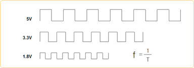
Signal line is a digital signal which is represented by a voltage of 1 and 0. The
problem is that fluctuation of low frequency power affects the signal line. In other
words, a fluctuation of power affects the signal line’s voltage.
This rule check can detect an existence of Analog Power plane on the same layer, or
up to 2 layers above or below from the target signal net.
Item: Enter the item name. This will be written in the report for
reference.
PWR/AGND: Select Power/Analog GND net from Net Group list.
Net: Select High Speed Signal Net Group.
Start Component/End Component: A test will be performed between the start
component and the end component.
Pin Escape: Enter a radius of circular region around pins to be excluded for
the rule check.
Via Escape: Enter a radius of circular region around vias to be excluded for
the rule check.
Clearance: Set a clearance for each Net Group on the same layer.
L1 Clearance: Set a clearance to the nearest layers above and below.
L2 Clearance: Set a clearance to the 2nd nearest layers above and
below.
Minimum: Report the shortest point of each segment, otherwise report all
failed point of each segment.
Composite Net: DFE uses composited power net instead of single power
net.
Passive Comp: The DFE makes a composite net for which are connected
through this passive component.
Exception Net: Nets which should not be merged into the composite
net.
Parallel Only: The DFE will check only the parallel section of target
nets.
GND Net If the GND Net exists between power net and signal net, the result
will be excluded.
Results include: Distance from the ground plane to the signal if the distance is less
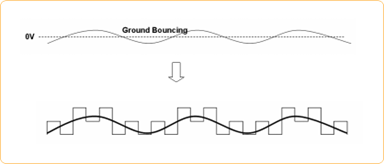
than a given value and defined clearance and actual distance.Figure 1. In low power clock signal case, when analog ground is falling to 0V, adjacent
clock signal may also bounce(falling) affected by ground falling.Figure 2.