Mechanical Pins
Define the shape and properties of mechanical pins.
-
Click .
The Mechanical Pins dialog opens.
- Pin Name: The name of the mechanical pin.
- Lead Shape: The type of the pin shape.
- Edit Lead: Edit the pin shape and size.
- X, Y: Show and edit the pin coordinate.
- Locate: Place the selected mechanical pin.
-
Edit Lead: Edit the pin shape and size.
-
Click Edit Lead to edit the pin shape.
Figure 1. 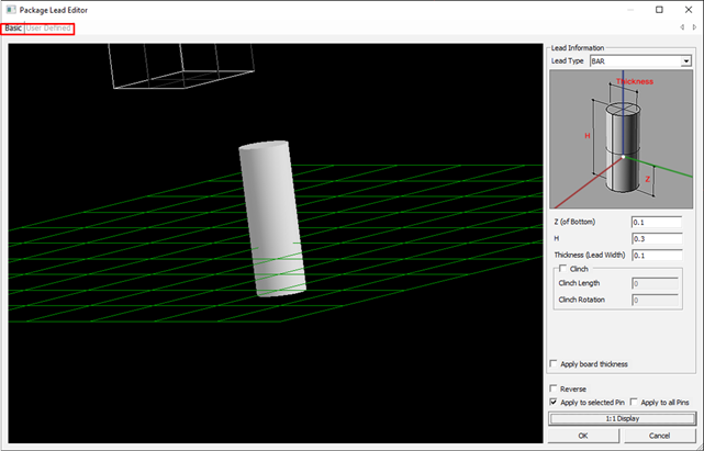
- Basic mode: Edit the pin shape with pre-defined shape.
- User Defined mode: Edit the pin shape with arbitrary shape editor.
-
Click Edit Lead to edit the pin shape.
-
Edit the pin shape in Basic mode:
-
Select the predefined pin shape and define the size of the pin.
The predefined pin shapes are shown below.
Type Shape Type Shape JBEND Figure 2. 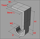
BUTT Figure 3. 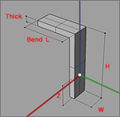
Reverse BUTT Figure 4. 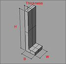
FLAT Figure 5. 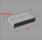
GULLWING Figure 6. 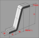
GULLWING-A Figure 7. 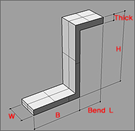
Round GULLWING Figure 8. 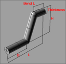
WRAPAROUND Figure 9. 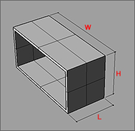
BAR Figure 10. 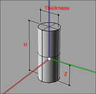
Round BAR Figure 11. 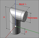
Round BAR-A Figure 12. 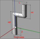
Round BAR-B Figure 13. 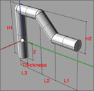
Round BAR-C Figure 14. 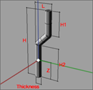
BALL Figure 15. 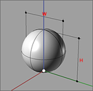
DIP Figure 16. 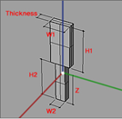
DIP-A Figure 17. 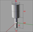
DIP-B Figure 18. 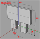
Kink DIP Figure 19. 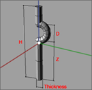
Kink DIP-A Figure 20. 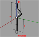
Round DIP Figure 21. 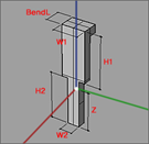
Round DIP-A Figure 22. 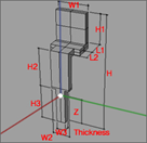
CBEND Figure 23. 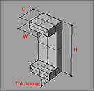
J Inverted Figure 24. 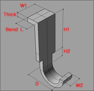
WIRE Figure 25. 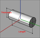
-
Select the predefined pin shape and define the size of the pin.
-
Edit pin shape in User Defined Mode.
Figure 26. 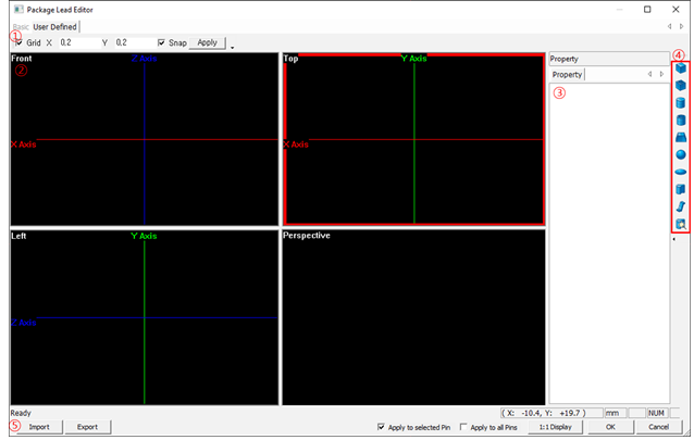
-
Property: Display and edit the properties and positions of the pin
shape.
Figure 27. 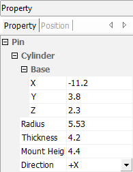
- In the Property dialog, click the
Position tab to display the position
of the pin.
Figure 28. 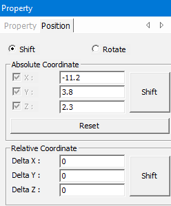
- Absolute Coordinate: Display and edit the absolute coordinate of the pin.
- Shift: Move pin shape to defined coordinate.
- Reset: Initialize the input values.
- Relative Coordinate: Display and edit the relative values to move the pin.
- In the Property dialog, click the
Position tab to display the position
of the pin.
-
Rotate: Select the Rotate radio button.
Figure 29. 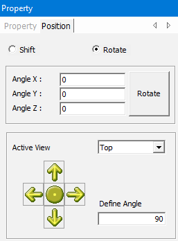
- Rotate: Rotate the pin shape with defined angles.
- Active View: Select the view direction to reference.
- Define Angle: Define the rotation angle for each click.
-
Property: Display and edit the properties and positions of the pin
shape.
-
Draw tools: Draw and edit the shape of the pin.
Figure 30. 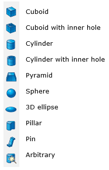
- Locate: Place the selected mechanical pin.