ArrayOnSurface
This is an option to create an array from planar elements conformed to the selected surface.
Defining the cell structure on XY Plane and centered at the origin is the first step. In the example below, a disk with center in 0,0,0 and radius 0.04 is considered.
The next step is the creation of the object or surface where the cell structure will be placed on. For example, a sphere is created with center in 0,0,0 and radius 0.5, then it is exploded for extracting its surfaces.
Now click on Edit - Geometric Operations – Arrays – ArrayOnSurface option to start with the array generation.
The command ask the selection of the surfaces where the cell will be placed. This selection is only valid over surfaces entities, so objects should be exploded before using the command.
The first required option is the mode of array generation. Four different ways of cell distributions are available:
- Parametric This option generates a quasi-regular distribution of cells along the parametric dimensions of the surfaces, i. e., the cells sizes may vary in the surfaces but the structure shape is guaranteed. It is recommended for non-degenerated surfaces or when the size of the cell in X and Y dimension must be different.
- Global This option generates a more regular distribution of cells on the surfaces, i. e., the cells sizes and the structure shape may be slightly varied but the global quality of the array is improved. It is recommended for most of structures but it is only available when the size of the cell in X and Y dimension are identical.
- Projected This option generates a full regular distribution of cells along the reference plane and then they are projected onto the target surfaces, i. e., both the cells sizes and the structure shape are guaranteed whenever the curvature of the surfaces is soft enough. It is only recommended for soft-curvature surfaces. When this mode is selected, the command ask whether the cells have to be projected onto the surfaces bounds or not:
-
- Yes (by default) option generates and projects the cells on full surfaces, and the bounding cells are trimmed.
- No option only generates cells on the rectangles (Tx Ty) that are completely inside the surfaces.
- Manual This option place cells on the closest point on the surfaces to the introduced by the user, i. e., both the cells sizes and the structure shape are guaranteed whenever the curvature of the surfaces is soft enough in the selected points. It is recommended for customizing the cells distribution in most of structures.
The next parameter required is the type of array. Two different types of array types are available:
- Capacitive Metallic cell structures are generated as the original one.
- Inductive: Metallic cell structured are inverted to the original one, i.e., the generated cells are rectangular cells with holes with the shapes of the original cell.
Then, the size of the cell structure (in the units selected) is required. As a planar cell is considered, the size in X and Y dimensions are required. In the considered example, 0.1, 0.1 are introduced.
When the sizes of cell structure in X and Y are different, the global option returns an error because the two sizes must be identical for this mode.
The last parameter required is the selection of the planar object used as reference cell. Note that these objects must be centered at the origin of coordinates, contained in the XY plane and surrounded by the red rectangle (of Tx Ty sizes) highlighted. If multiple surfaces are required for the cell definition, all of them must be grouped in one unique object.
When the array operation is finished, the original surfaces and cells are in the geometry. It may be removed by using the Delete command.
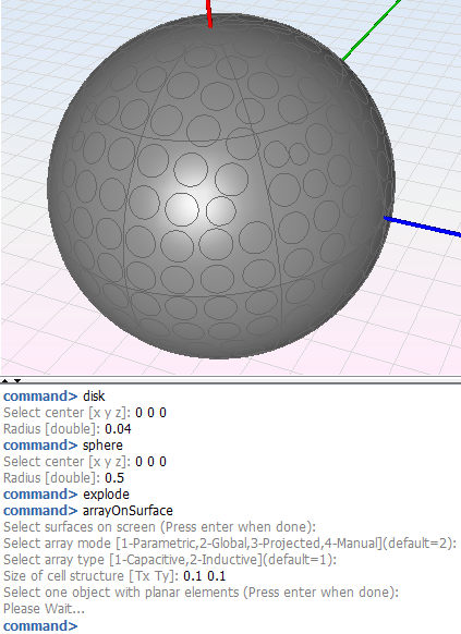
The next figure shows the full example of the disk array on the sphere with all the parameters required by default (the original objects have not been deleted).
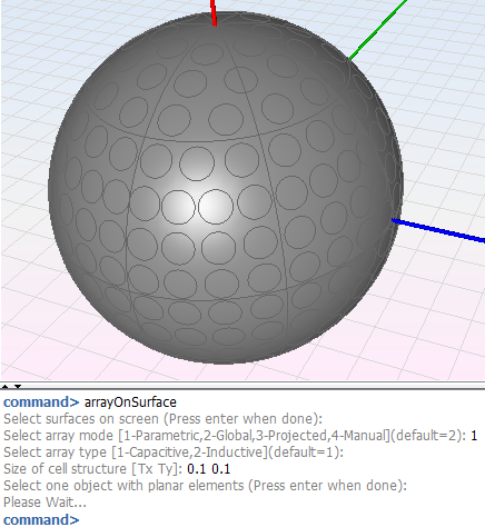
The next figure shows the full example of the disk array on the sphere generated with parametric mode (the original objects have not been deleted).
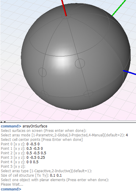
The next figure shows the full example of the disk array on the sphere generated with manual mode (the original objects have not been deleted).
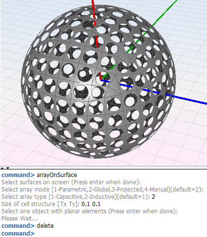
The next figure shows again the full example of the disk array on the sphere generated with the global mode and the inductive type (the original objects have been deleted).
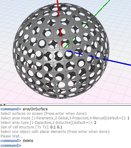
The next figure shows the full example of the disk array on the sphere generated with the parametric mode and the inductive type (the original objects have been deleted).
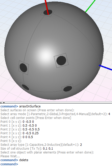
The next figure shows the full example of the disk array on the sphere generated with the manual mode and the inductive type (the original objects have been deleted).
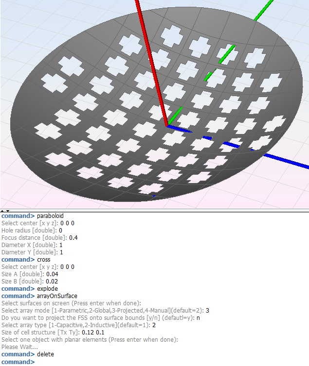
In the last part of this section, a paraboloid is considered to evaluate the generation of a crosses array with the projected mode.
The next figure shows the full example of the crosses array on the paraboloid with the rest of required parameters by default (the original objects have not been deleted).
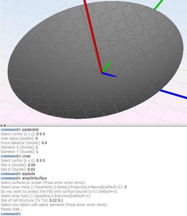
The next figure shows the full example of the cross array on the paraboloid without projecting onto surface bounds, and the rest of required parameters by default (the original objects have not been deleted).
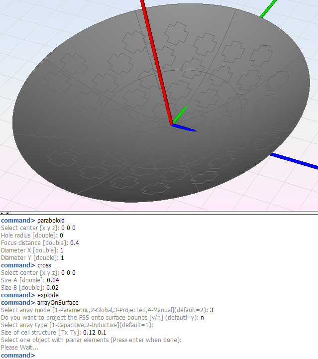
The next figure shows the full example of the cross array on the paraboloid with inductive mode and the rest of required parameters by default (the original objects have been deleted).
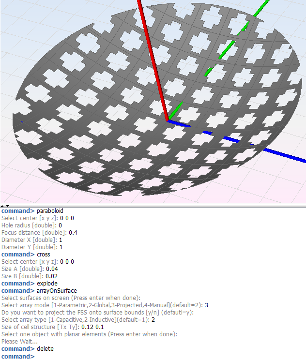
The next figure shows the full example of the cross array on the paraboloid without projecting onto surface bounds inductive mode, and the rest of required parameters by default (the original objects have been deleted).
