Thermal settings
Overview
In the thermal settings, depending on the considered test, you have the following possible configuration:
You can define the winding temperatures, bar and end ring temperatures or define the physical properties of the materials needed to run the tests without any thermal computation.
The workflow of the process is described hereafter.
 |
| Thermal setting for all the tests without thermal analysis |
In the current version, thermal solving modes are not available for any test.
Thermal settings
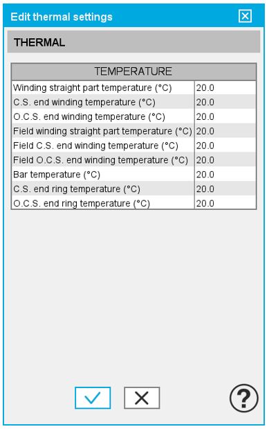
One must define the winding temperatures to make the corresponding material physical properties updated.
For Synchronous Machines with wound field – Inner salient pole, field winding and damper circuit temperatures must be defined.
Temperature of windings
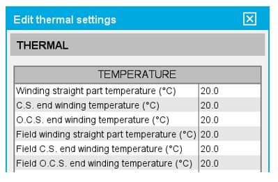 |
| Settings of winding temperature |
- Winding active length temperature (part 1S & 1R)
- Connection Side (C.S.) end winding temperature (part 2S & 2R)
- Opposite Connection Side (O.C.S.) end winding temperature (part 3S & 3R)
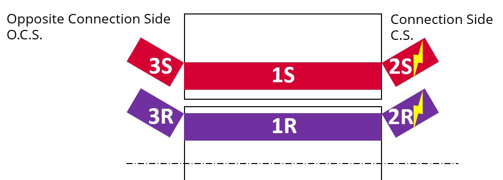 |
| Definition of the main parts of winding |
- Winding straight part resistance (part 1S & 1R)
- Connection Side (C.S.) end winding resistance (part 2S & 2R)
- Opposite Connection Side (O.C.S.) end winding resistance (part 3S & 3R)
The resulting resistance for the whole windings (considering the three parts described above) is computed as phase resistance, line-line resistance and field resistance.
Temperature of bars and end rings
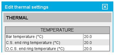 |
| Settings of bar and end ring temperature |
- Bar temperature (part 1)
- Connection Side (C.S.) end ring temperature (part 2)
- Opposite Connection Side (O.C.S.) end ring temperature (part 3)
 |
| Definition of the main parts of bars and end rings |
- Bar resistance (part 1)
- Connection Side (C.S.) end ring resistance between bars and between poles (if interpole connection exists) (part 2)
- Opposite Connection Side (O.C.S.) end ring between bars and between poles (if interpole connection exists) (part 3)
Flow chart of the tests without thermal solving mode
Below is the flow chart of computation, for test without thermal solving mode, available for all the tests.
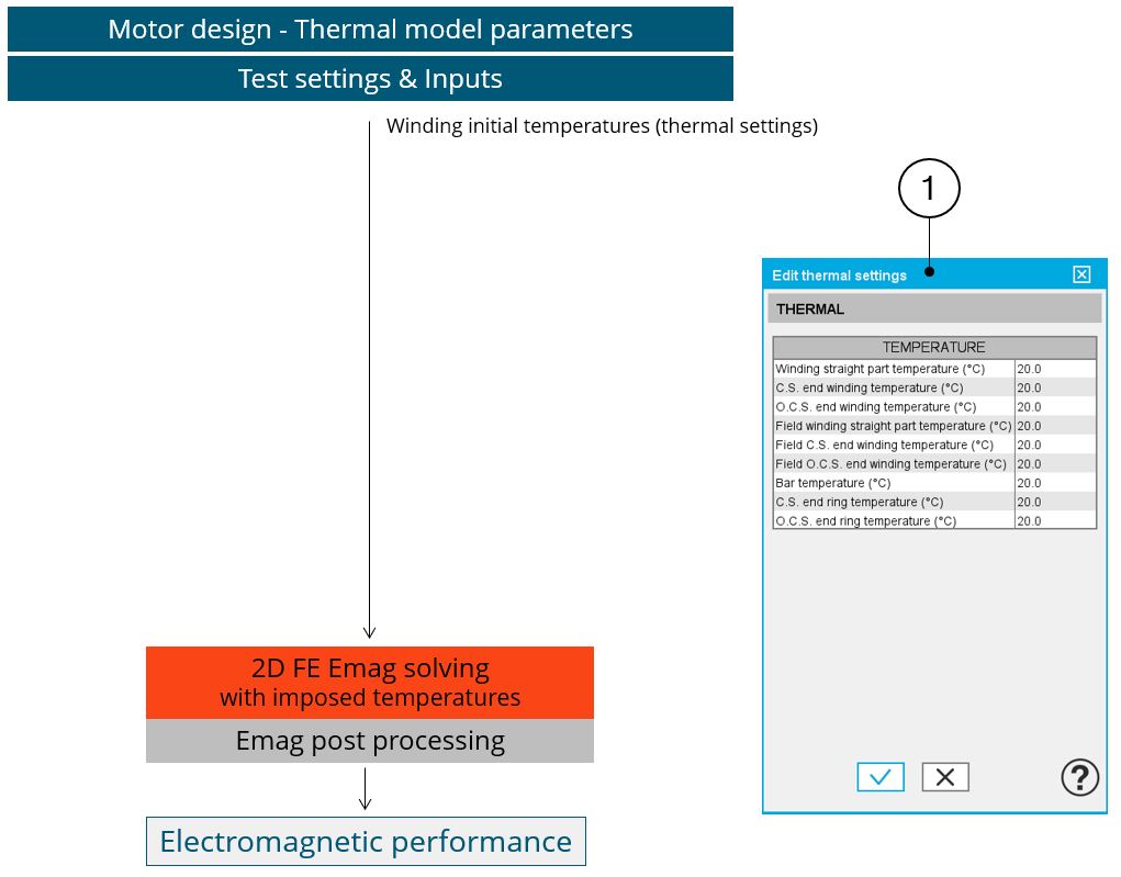 |
| (1) Thermal setting for all the tests without thermal analysis |