Defining the Antenna Site and Antennas
For this example, a single antenna site with three antennas is defined.
-
Specify the transmitter type and settings using one of the following
workflows:
- On the Project menu, click .
- On the Project toolbar, click the
 Set Site icon.
-
Under Settings, click 3 Sector
Site.
Figure 1. The Transmitter Type dialog. 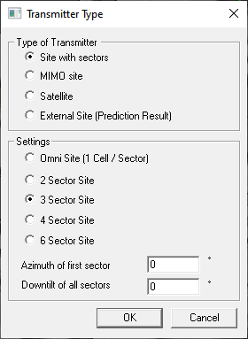
-
Click OK to close the Transmitter
Type dialog.
The mouse cursor is displayed as a circle to indicate that the Set site tool is enabled.
-
Click near point (X, Y) = (143.88, 187.90) in the 2D view to place the site
(the location of the antenna site is indicated by an orange circle).
Figure 2. A partial view of the 2D view. Place the antenna site at the location of the orange dot. 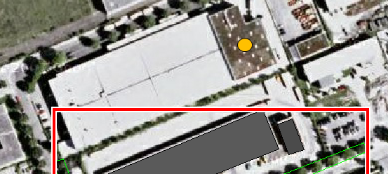
Note: The exact coordinates is not important for this example, but the above coordinate is used in the steps that follow.Tip: The coordinates at the current mouse cursor are displayed in the Status bar.The Site dialog is displayed. - In the z / Height field, enter a value of 5 m.
-
Click on Site 1 Antenna 1 to select and click
Edit.
The Cell dialog is displayed for antenna 1.
- Under Transmitter Settings, in the Frequency (used for propagation) field, enter a value of 1800 MHz.
- Under Location of Antenna, in the z / Height field, enter a value of 9 m.
- Under Antenna Pattern, click Directional / Sector antenna.
-
Under Antenna Pattern, click
Select to browse to the file
farfield_gain_3d.ffe1.
Figure 3. The Cell dialog for antenna 1. 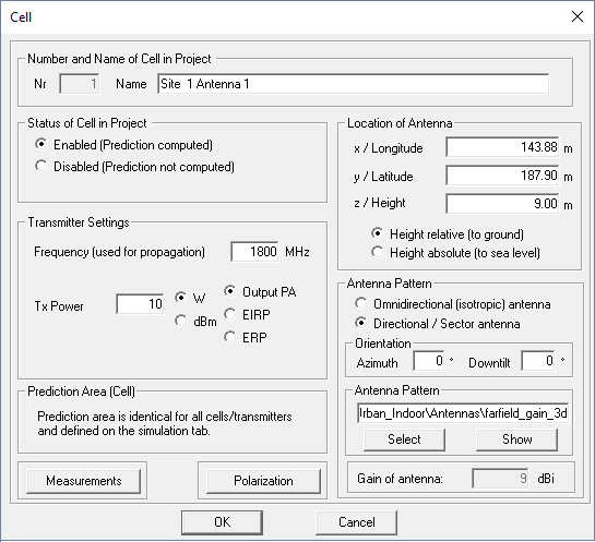
- Click OK to close the Cell dialog.
- Repeat Step 6 to Step 10 to define antenna 2.
-
Repeat Step 6 to
Step 10 to define
antenna 3.
Figure 4. The Site dialog. 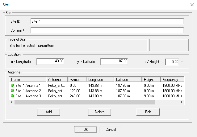
- Click OK to close the Site dialog.
-
Disable the Set site tool by clicking again on the
Set Site icon.
1 Project2_Hybrid_Urban_Indoor_Scenario\Antennas\farfield_gain_3d.ffe