Trim
Remove and edit a part of a surface or solid by projecting a profile curve onto it.
Create a Trim
Remove part of a surface or solid by projecting a profile curve onto it.
-
Click the Trim icon.
Edit a Trimmed Object
Edit the trim direction or extension distance.
-
Edit the trim:
To Do this Reselect objects to trim - In the guide bar, click Objects.
- Click the objects you want to add or remove.
- Right-click to confirm.
Force surface result This option forces a surface output when a solid object is used as input. 
Force Surface Result On

Force Surface Result Off
Select parts to trim In the guide bar, select the parts to trim: - Keep Both: Keep both parts of the trim essentially splitting the object.
- Keep Interior: Keep the trimmed part inside the trim curve.
- Keep Exterior: Keep the trimmed part outside the trim curve.
Define the reference direction In the Control Panel, next to Reference Direction, select one of the following options: - Global Z Axis: Trim along the global x-axis
- Global Y Axis: Trim along the global y-axis
- Global Z Axis: Trim along the global z-axis.
- Ref. Geometry: Set the trim direction by clicking a reference geometry.
- Normal Direction (default): Make the axis perpendicular to the trim curve's construction plane.
- Perpendicular to Surface: Only works with a single curve. The result will always be an open surface.
- Custom: Trim in a custom
direction by doing one of the following:
- Drag the arrows.
- Drag the direction point.
- Click Set as current view to project the trim curve(s) along the axis that is perpendicular (normal) to the current active view.
Extend the trim curve Turn on Extend when the trim fails as a result of the input curve ending within the bounding box of objects being trimmed. This option extends the trim curve on either one or both ends tangentially. 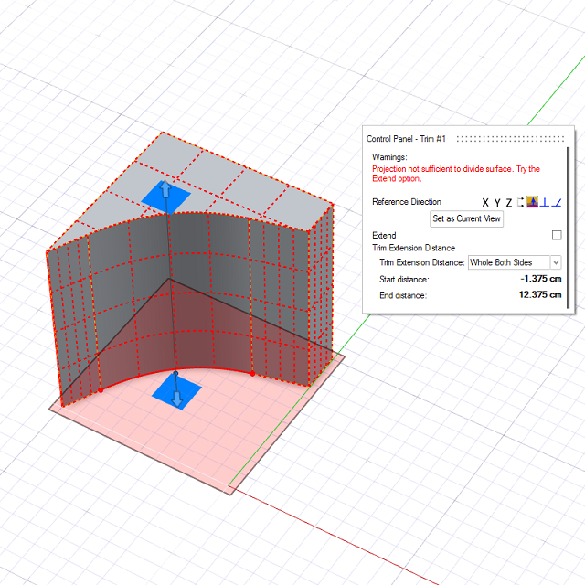

Change the trim extension type In the Control Panel, next to Trim Extension Distance, select one of the following options: - Whole Both Sides: Trim on both sides of the projected curve.
- Curve Normal: Trim only in the direction of the projected curve's normal.
- Inverse Curve Normal: Trim only in the direction opposite to the projected curve's normal.
- Custom Distance: Define a
custom vector by doing the following:
- Type a Start distance.
- Type an End distance.