Loft
Creates loft surfaces from the edges of flanges to complete the flange die creation.
-
Click the Flange Loft icon.

-
Select the Loft tool on the secondary ribbon.

-
Choose a selection method and then select the Flange
Edges (these are like the "profiles" in the regular Loft surface
tool). Selectable edges are green.
If you select this method Then do this Chain selection (default) Click an edge and all connected edges are selected automatically. Tangent selection Click an edge and the tangent edge is also selected automatically. Single selection Click an edge. Standard selection When you click an edge, all connected edges are automatically selected. To reselect the flange edges, in the guide bar, select Clear Selection , and then select different flange edges.
 -
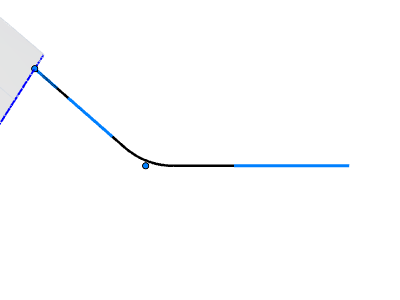
Select a rib type:
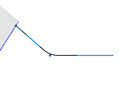
- Start with Line (default): The rib extends from
the part with a line with tangent continuity and drops down to the
binder with a smooth fillet between them.

The rib is parametric. To edit the dimensions, select the respective handles.
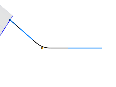
- Start with Arc: The rib extends from the part
with an arc, ensuring tangent continuity, and drops down to the binder
with a smooth fillet between them.
The rib is parametric. To edit the dimensions, select the respective handles.
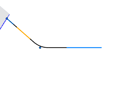
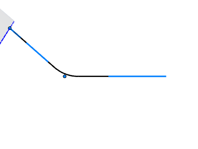
- Line with Arc: The rib extends from the part with
a line, ensuring tangent continuity, and then follows with an arc and
flat before dropping down to the binder with a smooth fillet between
them.
The rib is parametric. To edit the dimensions, select the respective handles.
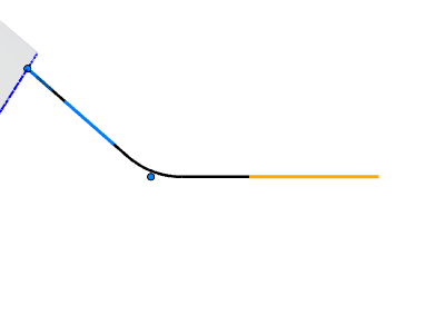
- Straight Line: The rib extends from the part with
a line, ensuring tangent continuity, and is continuous down to the
binder. Tip: You can align Straight Line ribs with an existing edge using the Reference Edge option detailed below.
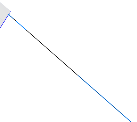
The rib is parametric. To edit the dimensions, select the respective handles.
- Start with Line (default): The rib extends from
the part with a line with tangent continuity and drops down to the
binder with a smooth fillet between them.
-
Adjust the flange loft:
To Do this Note Edit the ribs In the guide bar, select Edit Ribs. You can add, delete, and adjust ribs. - To add ribs at custom locations, first hold down Alt while hovering over an addendum start edge, and then click a blue or green dot. A green dot indicates a sharp corner where edge continuity is broken.
- To delete a rib, select it and press Delete.
- To adjust a rib, select it and configure the options in the microdialog or Control Panel. See Rib Options.
Interactively edit rails By default, rails are created automatically (Auto create rails is selected in the Control Panel). - In the guide bar, select Interactively edit rails.
- Do one of the following:
- Hover over the rail to display handles. You
can do the following:
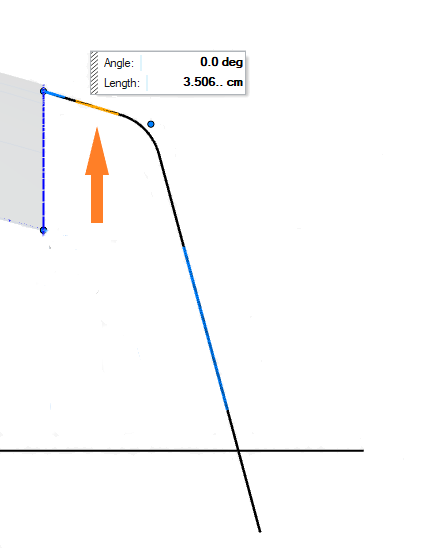
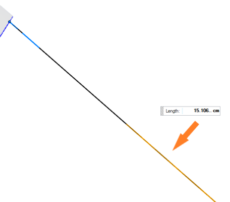
- Drag the upper arrow to change the length of the addendum extension from the part.
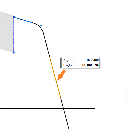
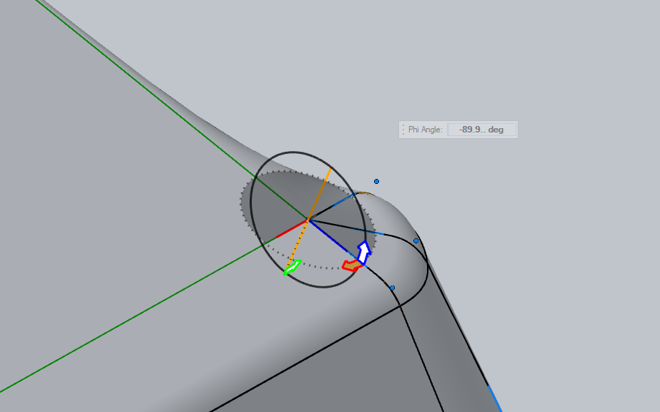
- Drag the lower arrow to change the angle of the rib plane.
- Select a handle and enter an Angle or Length in the microdialog.
- Hover over the rail to display handles. You
can do the following:
Copy some parameters of a source rib to target ribs - In the guide bar, select Pass Rib Parameters.
- Select the source rib.
- To select the target ribs, do one of the
following:
- Alt+click
- Right-click, and then select Select ribs except source or Select ribs of same type.
- To copy the parameters from the source to targets, right-click, and then select Update.
The following parameters are passed on: - Addendum configuration
- Angle
- Length
- Tangency (G1) to the part
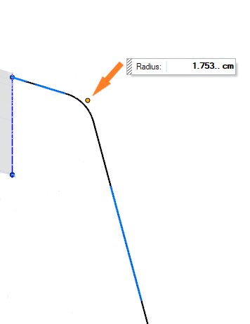
- Radius
- Rib plane orientation
- Align to XY draw plane
See Rib Options for parameter definitions.
Create a copy of a rib - In the guide bar, select Copy Rib.
- Select the rib to copy.
- To paste a copy of the rib, Alt+click.
Automatically align ribs to a source rib - In the guide bar, select Auto-align Ribs.
- Select the source rib.
- To select the ribs to align, do one of the
following:
- Alt+click
- Right-click, and then select Select ribs except source or Select ribs of same type.
- To align the ribs, right-click, and then select Update.
Using this option, you can basically copy the following parameters from the source ribs to the target ribs: - Rib plane orientation
- Align to XY draw plane
Translate or rotate the rib plane If none of the options to automatically align the ribs produces the desired result, use the graphic manipulator to reposition the rib plane. - In the guide bar, select Edit Ribs.
- Click and drag one of the red, green, or blue arrows to rotate the rib plane around the corresponding colored axis. The angle measures the rib angle with respect to the corresponding axis.
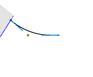
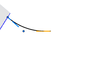
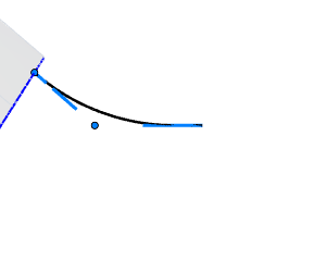
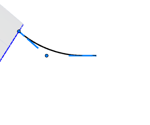
Align Straight Line ribs with an existing edge - Do one of the following:
- Select the Straight Line ribs you want to align.
- Select the desired rib and, in the guide bar, change the rib type to Straight Line.
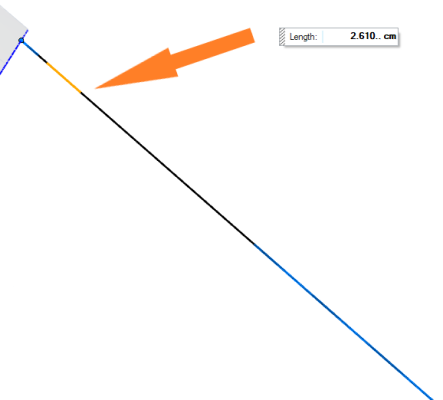
- In the guide bar, select Reference Edge.
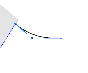
- Select the reference edge. Tangency is maintained
between the straight line ribs and the reference
edge, so if the straight line edge is next to the
reference edge, they become one continuous edge.
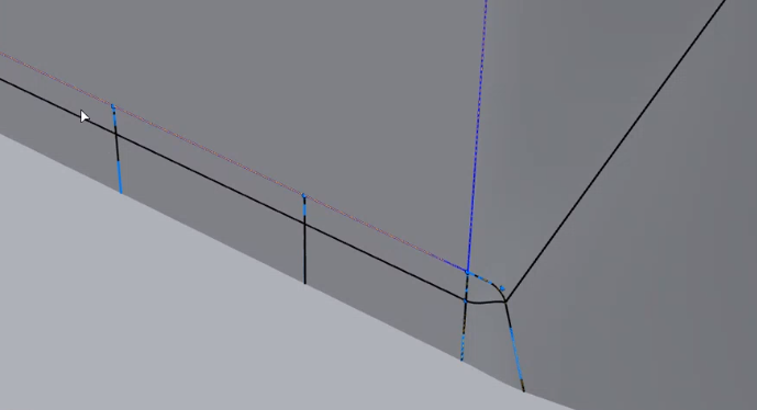
Figure 1. The Straight Line edge (black and lighter blue) and the Reference Edge (cobalt blue) are now like one continuous edge