
Run Analysis
Define settings and execute an analysis of a foaming part design. Generate results for individual or combined events.
- You can select which result types the analysis will calculate in your Preferences settings under . If you enable fewer result types, the analysis will take less time.
- You can combine results staged in your Preferences settings under .
- Analysis results are saved in the folder specified in your Preferences settings under .
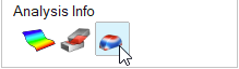
- Click the Foaming tab on the ribbon.
-
Click Run Analysis on the Analyze
icon.

-
Define settings on the Preferences and Customized Results tabs of the Run
Analysis dialog.
-
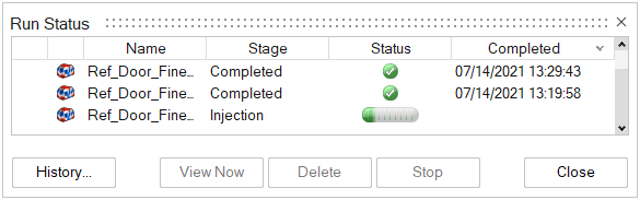
Click Run.
The run status is displayed.
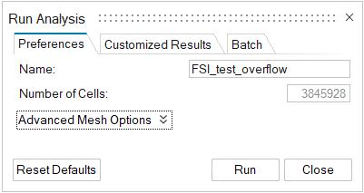
Preferences
Use the Preferences tab on the Run Analysis dialog to define the run and advanced-mesh options for your analysis.
Preferences Tab: Run Options
| Option | Description |
|---|---|
| Name | Type the name of the run. By default, the name of the model is used. |
| Number of Cells | This value reflects the number of cells in the voxel mesh. The value is based on the defined Number of cells along axis, Uniform size of cells, or Variable size of cells. Lower numbers reduce run time. Higher numbers increase accuracy. |
| Use symmetry | Save analysis time by only calculating the simulation for
half of a symmetrical part. Note: This
option is note recommended for asymmetrical
parts. |
| Edit symmetry | Reorient or translate the plane of symmetry. |
| Reset Defaults | Define the mesh with the default values. |
| Mesh preview | View a preview of the part's mesh based on current settings. |
| Run | Launch the simulation. |
| Close | Close the dialog. |
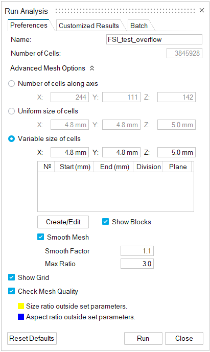
Preferences Tab: Advanced Mesh Options
Click the chevron ![]() to show the Advanced Mesh Options.
to show the Advanced Mesh Options.
| Option | Description |
|---|---|
| Number of cells along axis | Select this mesh option to produce a 3D matrix of voxel cells. Enter the number of cells along the X, Y and Z-axes. |
| Uniform size of cells | Select this option to create a mesh with uniform cells. Enter the size of cells along the X, Y and Z-axes. 5 mm is the recommended size for most situations. |
| Variable size of cells | Select this option to create a mesh-refinement zone for a
particular region of the part. Enter the size of cells along the
X, Y and Z-axes (5 mm is the default value). Enter the zone
parameters in the table. Apply settings and define parameters
specific to this option:
|
| Speed/Accuracy | Prioritize calculation speed or precision in the analysis. A faster analysis will be less precise; a more precise analysis will take more time to run. |
| Show Grid | Select this option to display the grid for the entire part. |
| Check Mesh Quality | Select this option to ensure that your mesh cells' aspect
ratio and critical size ratio are within set parameters.
Note: You can set the parameters for
size ratio and aspect ratio in . 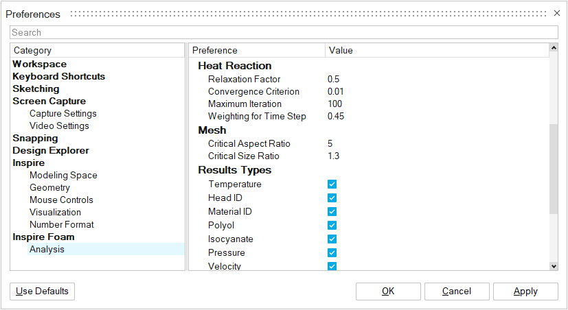 |
Meshing Recommendations
- When using a static nozzle, set the size of the mesh cells to 33% of the nozzle's diameter or less. For example, if the static nozzle's diameter is 12 mm, set the mesh size to 4 mm or less.
- When using a moving nozzle, set the size of the mesh cells along the nozzle's path to 20% of the nozzle's diameter or less. For example, if the nozzle's diameter is 15 mm, set the mesh size to 3 mm or less.
- When the foam part includes regions that are very thin, enable Variable Size of Cells and ensure that the thin regions have at least 3 mesh cells. For example, for a region that is 3 mm thick, set the mesh size to 1 mm.
- If the model includes non-foam parts (inserts or Velcro parts), only one mesh cell is required for those parts. For example, if an insert is 10 mm in diameter, the mesh size for the insert can be 10 mm.
Customized Results
Use the Customized Results tab on the Run Analysis dialog to define specimens, sensors, and output intervals for your analysis.
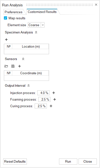
Map results: Enable this option to generate a tetrahedral mesh that will show results closer to the actual shape of the part.
Element size: Select Coarse or Fine. Fine will yield more precise results, but the analysis will take more time to run.
Customized Results Tab: Specimen Analysis Options
Click the chevron ![]() to show the Specimen Analysis options.
to show the Specimen Analysis options.
| Option | Description |
|---|---|
| Specimen Analysis | The Specimen options let you define a zone of particular interest on the part or mold from which analysis results can be generated. |
 |
|

Customized Results Tab: Sensors Options
Click the chevron ![]() to show the Sensors options.
to show the Sensors options.
| Option | Description |
|---|---|
| Sensors | Place sensors on your model from which results can be generated for specific locations on the model. |
 |
Select the Import button to open an existing sensor definition from a .csv or .txt file and apply it to your current model. |
 |
Select the Export button to save defined sensors to a .csv or .txt file. |
 |
Select the Plus button to create a new sensor. Drag the arrows to position the sensor or enter coordinates in the microdialog. |
Use the Callouts icon ![]() in the Analysis Explorer to view sensor data.
in the Analysis Explorer to view sensor data.
Customized Results Tab: Output Interval Options
Click the chevron ![]() to show the Output Interval options.
to show the Output Interval options.
| Option | Description |
|---|---|
| Injection process | Set the output interval to be written when the injection process reaches the defined percentage of completion. |
| Moving parts process | Set the output interval to be written when the moving parts
process reaches the defined percentage of completion. Note: This option is available only when
Moving Parts is enabled in the Advanced tab of the Process
Parameters window. |
| Foaming process | Set the output interval to be written when the foaming process reaches the defined percentage of completion. |
| Curing process | Set the output interval to be written when the curing process reaches the defined percentage of completion. |
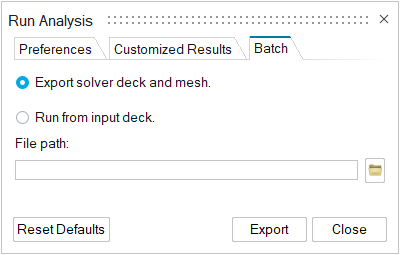
Batch
Use the Batch tab on the Run Analysis dialog to export model files for direct editing or to run an analysis from specified files.
| Option | Description |
|---|---|
| Export solver deck and mesh | Save files associated with the model for direct editing. |
| Run from input deck | Run an analysis using files specified in the File path field. |
| File path | Change the directory path for the export destination or input source. |
| Reset Defaults | Restore default values for the analysis run. |
| Export | Run the analysis with the defined parameters. |
| Close | Close the dialog. |