Use the Process Parameters icon to define the ending condition of the simulation,
define a parting line, and set up the model for tilt pouring, centrifugal foaming, or
moving mold parts.
Location: Foaming ribbon,
Process icon
Basic
Use the Basic tab to define the conditions for ending a simulation.
Ending Conditions
Set the conditions to end your analysis with these parameters:
Parameter
Description
Filled Volume
End the simulation when the material volume in the mold
reaches the specified percentage.
Gelling Rate
End the simulation when the gelling rate of the material
reaches the specified percentage.
Time
End the simulation when the filling time exceeds the input
value.
Parting Line
Enable this option to define the mold's parting line gap, and
if desired, define variations in the gap thickness over
time.
Gap Thickness
Enter the gap thickness between mold parts.
Variable Thickness
Enable this option to define variations in the gap thickness
over time. The first column in the table is time in seconds from
the beginning of the process. The second column is the length of
the gap at that time in the process.
Insert and delete rows in the data table for variable
thickness:
The table defaults to five rows. The default value for
the first row is 1.0 seconds in the time column and 1.0
mm in the thickness column, with each subsequent row
showing an increase of 1 second and 1 mm.
Select the first button to insert a row in the table
after the selected row.
Select the second button to insert a row in the table
after the last data point.
Select the third button to delete a selected data point
in the table.
Air Vents
Include defined air vents in the simulation.
Air Back Pressure
Include back pressure in the simulation.
Note: This is not available unless the
Air Vents option is
enabled.
Initial Pressure
Change the initial back pressure setting. The default value
is one atmosphere.
Activate Time
Change the moment when back pressure will engage. Enter a
time in seconds from the start of the process.
Advanced
Use the Advanced tab to define tilt-pouring, centrifugal foaming, or moving parts
events for a foaming analysis.
Tilt Pouring
Select the option for Tilt Pouring on the Advanced tab and
define the parameters in the microdialog.
Parameter
Description
Select and manipulate the Move tool to
define the mold-tilting location, or enter the X, Y and Z
coordinates in the microdialog.
Rotation Axis
Select the axis to orient the tilt of the mold.
Preview
Play an animation of the of the tilt-pouring
rotation.
Time
Enter the start time for each tilt-pouring event.
Angle
Enter the angle of the tilt relative to the current position
of the mold.
Insert and delete rows in the data table for tilt pouring:
Select the first button to insert a row in the table
after the selected data point. The default value is 5
seconds followed by divisions of .5.
Select the second button to insert a row in the table
after the last data point.
Select the third button to delete a selected data point
in the table.
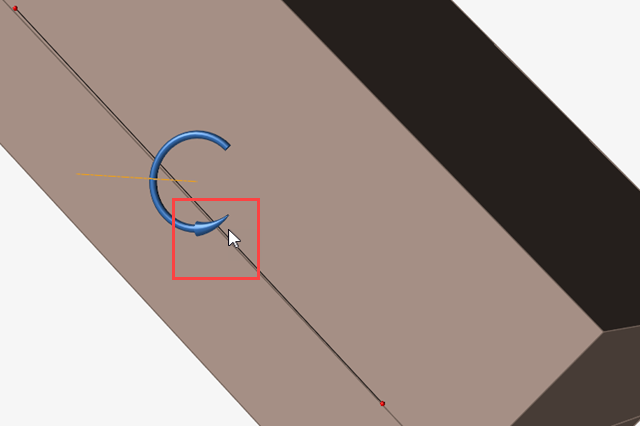
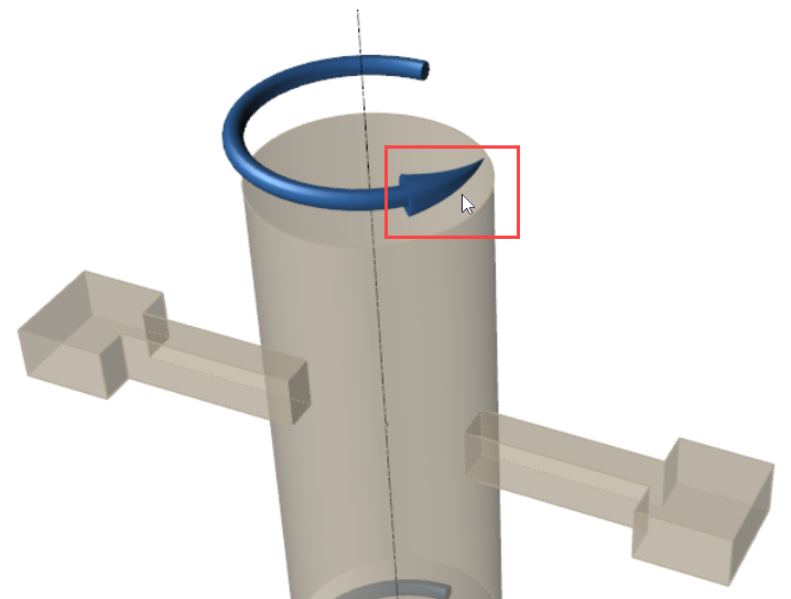
To reverse the rotation of the tilt, double-click the arrow that indicates
the tilt direction on the model.
Centrifugal Foaming
Select the option for
Centrifugal Foaming on the Advanced tab and define the
parameters in the microdialog.
Parameter
Description
Select and manipulate the Move tool to
position the rotational axis, or enter the X, Y and Z coordinates in
the microdialog.
Rotation Axis
Select the axis to orient the rotation of the mold.
Time
Enter the start time for each change in angular velocity.
Angular Velocity
Set the mold's angular velocity at different times during the
process.
Insert and delete rows in the data table for centrifugal
foaming:
The table defaults to two rows. The default value for both
columns in the first row is 0. The default value for the
Time column in the second row is 5 seconds. The default
value for the Angular Velocity column in the second row is
60.
Select the first button to insert a row in the table after
the selected row.
Select the second button to insert a row in the table after
the last data point.
Select the third button to delete a selected data point in
the table.
To reverse the rotation of the mold, double-click the arrow that indicates the
rotational direction on the model.
Moving Parts
Select the option for Moving Parts on the Advanced tab and
click the Add moving parts button to open the Moving Parts
dialog. In the Moving Parts dialog, use the controls to designate mold parts that
will move and define their motion.
Parameter
Description
Preview
Click this button to view an animation of the moving
parts.
Use Overflow
Enable this option to create an area for excess material to
flow into.
Edit
Click the Edit button to change the
dimensions and position of the overflow box.
Use the Dimensions fields to define the overflow box's
length, width, and height.
Use the Coordinates fields to position the faces of the
overflow box in three dimensions.
Add rotation button
Click this button to select a mold part that will rotate
during the process. Right-click and mouse through the check mark to exit, or double-right-click. Use the
controls that appear to define the part's motion.
Axis menu
Select a global axis for the part to rotate about.
Use the move tool to reposition the part's rotational
axis.
Select an edge to guide the moving part's motion. Right-click and mouse through the check mark to exit, or double-right-click.
Angle field
Define the part's rotational motion in degrees.
Choose the start point, axis point, and end point of the
part's angular motion. Right-click and mouse through the check mark to exit, or double-right-click.
Add displacement button
Click this button to select a mold part that will move
linearly during the process. Right-click and mouse through the check mark to exit, or double-right-click. Use the controls that appear to define the part's motion.
Direction menu
Select a global axis for the part to move along.
Select an edge to guide the moving part's motion. Right-click and mouse through the check mark to exit, or double-right-click.
Distance field
Define a distance for the part to move.
Choose the start point and end point of the part's linear
motion. Right-click and mouse through the check mark to exit, or double-right-click.
Start Time field
Define the time when the part will start moving in seconds
from the beginning of the process.
End Time field
Define the time when the part will stop moving in seconds
from the beginning of the process.
Delete this instance of motion.
Note:
If the Start Time and End
Time fields are not populated, the part will not move.
You can designate a mold part to move both linearly and rotationally at
the same time.
While it is possible to select more than one mold part for the same
instance of motion, it is better to define each mold part's motion
separately.