Create Arbitrary Part and Assign Simulation Model
-
Click OK.
The Electrical & Thermal Properties dialog opens. You can assign the simulation model for this part in the dialog.
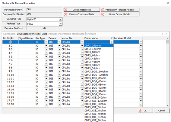
Figure 1.- Device Model File: Specify/register the IC models in the form of IBIS, SPICE, Linear Device, S-Parameter, Package Parasitic and Y/Z parameters. To register and use the model in Linear Device form, this model should be prepared using the Linear Device Modeler menu. The model in the form of Package Parasitic should also be prepared using the Package Pin Parasitic Modeler menu.
- Passive Component Data: Specify the part values in the form of RLC, SPICE and S-Parameter.
- Package Pin Parasitic Modeler: Enable to define package pin’s RLC parasitic model having versatile sections and branches.
- Linear Device Modeler: Enable to define simple linear device model for IC pin which will be worked as one of the types among Input, Output, IO, or Terminator.
-
To define a new linear device model or manage it, click Add in the Linear Device Modeler
dialog.
It is shown in the Model Names field. You can select the model type and assign proper properties.
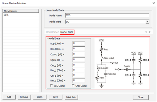
Figure 2.Note: Depending on the selected working type, you should define the bias and RLC values configuring the circuit topology.