Run Analysis
Define parameters and execute an analysis to understand filling, packing, cooling or warpage events during molding. Generate results for individual or combined events.
-
Click Run Analysis on the Analyze icon..

-
Define the parameters for the analysis.
Tab Option Description Stages Name Type the name of the run. By default, the name of the model is used. Element size Enter the average element size for the part cavity. The software creates the mesh based on this value. The default element size is based on average thickness * 1.8, with other factors taken into account. Compute Cycling Select to compute the number of cycles needed for the mold to reach working temperature. Click the  button to set the maximum
number of cycles to run and set the time the mold will
remain open between cycles.
button to set the maximum
number of cycles to run and set the time the mold will
remain open between cycles. Filling Selected by default. The filling stage examines the flow pattern, temperature, and pressures associated with the material entering into the mold. Packing Select to keep injecting fluid after filling to compensate for thermal contraction. This helps to reduce warpage and sink marks. Cooling Select to view cooling results in which solidification starts with a totally full mold and ends at a specified temperature or time. Warpage Select to examine evidence of warpage. Warpage can occur when a material shrinks non-uniformly due to high cooling rates, mold restraint, or temperature differences that create internal stresses. Note: You must select the Packing option to make Cooling available, and you must select Cooling to make Warpage available.Compute Fiber Orientation Select the Compute Fiber Orientation option to include fiber orientation in the analysis. Click the
button to customize the
fiber orientation calculations in the
Fibers window.Note: Compute Fiber Orientation is disabled unless the part's material has fiber properties defined.Configuration Filling, Packing, Cooling HTC Enter the Heat Transfer Coefficient. W/m2K for each stage of the process. Room temperature Enter the ambient temperature of the work environment Virtual mold temperature Set the desired starting temperature for the mold. Fibers WindowOption Description Kappa Adjust the effect that the shear rate has on the material's fibers. Enter a number between .01 and 1, where 1 indicates full shear rate effect. Interaction Diffusion Coefficient This coefficient prevents fibers from aligning completely in the direction of the main shear rate. Increase this coefficient if analysis results diverge from experimental results. This coefficient applies equally in all directions, and overrides the diffusion asymmetry coefficients, reducing the highest (closest to 1) diffusion asymmetry coefficient and increasing the lowest (closest to 0). Enter a number between 0 and 0.1 where a value of 0.1 will give results in which the fibers are aligned in no particular direction.
Diffusion Asymmetry Coefficients X: This factor modifies the Interaction Coefficient applied along the local axis with the greatest amount of fibers aligned along it. Enter a number between 0 and 1. Y: This factor modifies the Interaction Coefficient applied in the orientation direction perpendicular to local X with second highest amount of fibers aligned along it. Enter a number between 0 and 1
Z: This is the axis perpendicular to local X along which the least amount of fibers are aligned. Enter a number between 0 and 1.
Accept Run the simulation with the current fiber orientation settings. -
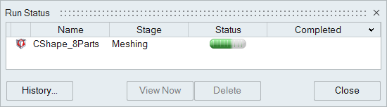
Click Run.
The run status is displayed.