Organizing the Land
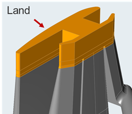
Organize the land corresponding to the number of layers in the model.
The solver requires each layer to have its own respective land region. Most of the time the land region will be a single solid after the flow volume is extracted. In this case, the land has to be organized corresponding to the number of layers in the model.
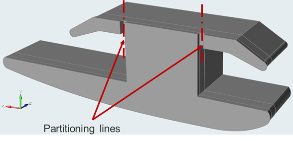
The land region is cut using partitioning lines. You can draw the appropriate line/curve using the Points/Lines or Arcs tool on the Geometry tab. If your CAD geometry already has the required trimming lines, then there is no need to create these lines/curve again.
Once you have created partitioning lines/curves, use them to trim the land solid.


- Click the Polymers tab.
-
Click the Cut Land icon.

-
Select the land part on the model, leaving Parts
selected.

-
Select the line to cut.
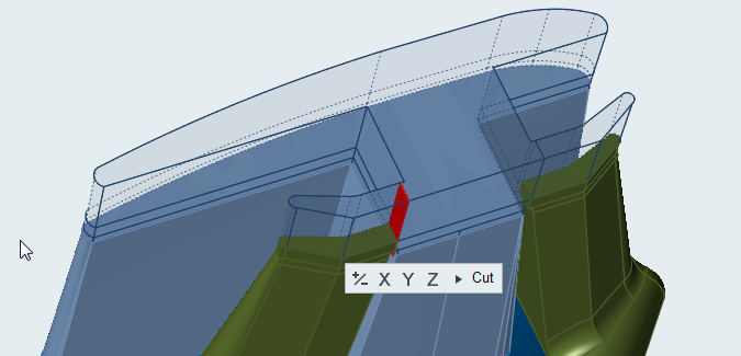
Upon selection of a valid part and line, you will see a preview of the desired cutting plane.

- Flip or change the direction of the cutting plane by clicking +/- or X,Y,Z in the microdialog.
-
Click Cut after finalizing the cutting plane.
The land is divided into two parts forming different layers.
-
Right-click and mouse through the check mark to exit, or double-right-click.
The partitioned parts will automatically be organized into the respective layers on exit.
Microdialog Options
Change the direction or alignment of a partitioning line and cut the land.
| Option | Description | |
|---|---|---|
| +/- |
|
Reverse the direction of the partitioning line. |
| X |
|
Align the partitioning line to the X axis. |
| Y | Align the partitioning line to the Y axis. | |
| Z | Align the partitioning line to the Z axis. | |
| Cut | Cut the land at the partitioning line. | |