OS-SL-T: 1070 Linear Static Analysis of a Plate with a Hole
Tutorial Level: Beginner In this tutorial, a plate with a hole is analysed.
Before you begin, copy the file(s) used in this tutorial to your
working directory.
The input model is already meshed and is stored in *.gda format.
The following exercises are included:
- Import the model into SimLab
- Define and solve the model setup
- View the results
Launch SimLab
Launch SimLab.
Import the Model
-
From the menu bar, click .
An Import File dialog opens.
- Select the plate_hole.gda file.
-
Click Open.
The plate_hole.gda file only contains geometric data.The plate_hole.gda file is loaded into the current SimLab database.
Define the Solution
-
From the Solutions ribbon,
Physics group, click the
Structrual tool.
The Create Solution dialog opens.
-
In the Create Solution dialog, complete the following and
click OK.
- For name, enter Solution_1.
- For Solver type, select OptiStruct.
- For Solution type, select Linear Static.
- For Select bodies, select the plate_hole body.
Figure 1. Create Solution 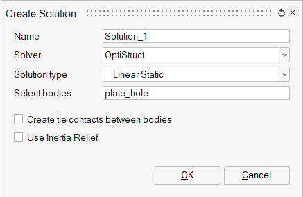
Define Constraints
- From the Analysis ribbon, Loads and Constraints group, click the Contraints tool.
-
From the secondary tool set, click the Fixed tool.
The Fixed Constraint dialog opens.
- In the Fixed Constraint dialog, enter SPCS for Name.
-
Enable all six checkboxes.
Figure 2. Define SPCS Constraint 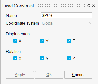
- In the modeling window, right-click and select Edge for the selection filter.
-
In the modeling window, select the two ends of the
plate of the plate.
Figure 3. Select Plate Edges 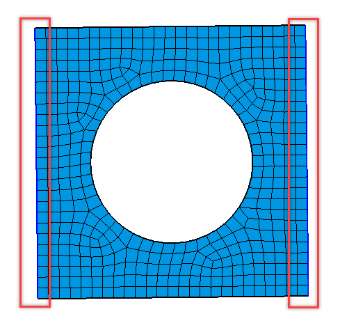
- In the Fixed Constraint dialog, click OK.
Apply Forces
- From the Analysis ribbon, Loads and Constraints group, click the Loads tool.
-
From the secondary tool set, click the Force and Moment
tool.
The Force and Moment dialog opens.
- In the modeling window, right-click and select Edge for the selection filter.
-
In the modeling window, select the circular edge as
shown below.
Figure 4. Select Circular Edge of Model 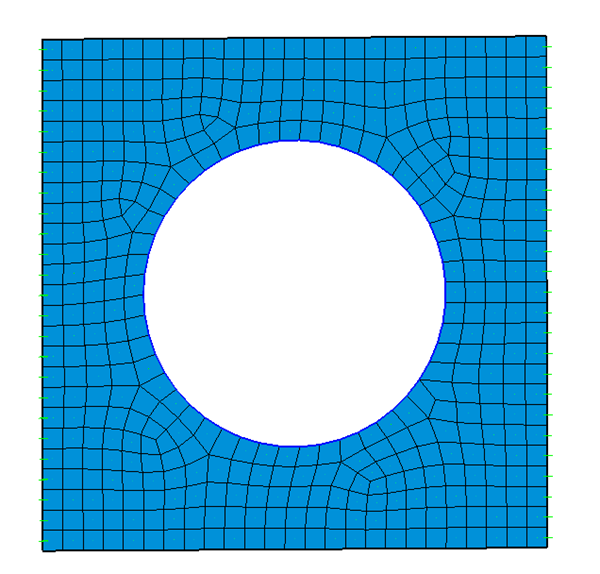
-
In the Force and Moment dialog, define the following
parameters and click OK.
- For Name, enter FORCE.
- For Z, enter 1000.
- For Distribute over nodes on face/edge, select Divide equally on all nodes.
Figure 5. Define Force and Moment 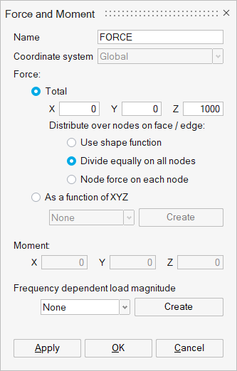
The total force of 1000N is distributed equally as 21.27N for the 47 nodes on the circular edge.
Apply Material and Apply Properties
-
In the Property tab of the Model Browser, double-click
the steel material.
The Material dialog opens.
-
In the Material dialog, define the following parameters
and click OK.
- For Name, enter STEEL.
- For Density, enter 7.9e-09
- For Youngs_modulus, enter 200000.
- For Poissons_ratio, enter 0.3.
Figure 6. Create Material 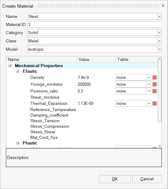
-
From the Analysis ribbon,
Property group, click the
Property tool.
The Analysis Property dialog opens.
- In the modeling window, select the plate_hole body.
-
In the Analysis Property dialog, define the following
parameters and click OK.
- For Name, enter PLATE_HOLE.
- For Entity, select Shell.
- For Material, select Steel.
- For Thickeness, enter 10.
Figure 7. Create Property 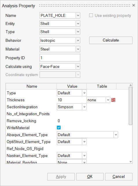
The material property is applied to the body.
Solve and View Results
Solve the Solution
From the Solutions tab of the Model Browser,
right-click Results under the Solution_1 and select
Update from the context menu.
The Solution begins to solve. Once solved, the results are automatically
loaded back into the database.
Interpret the Results
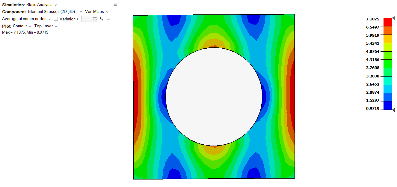
Once solved, the results display.Figure 8. Example Displacement Results (Resultant)
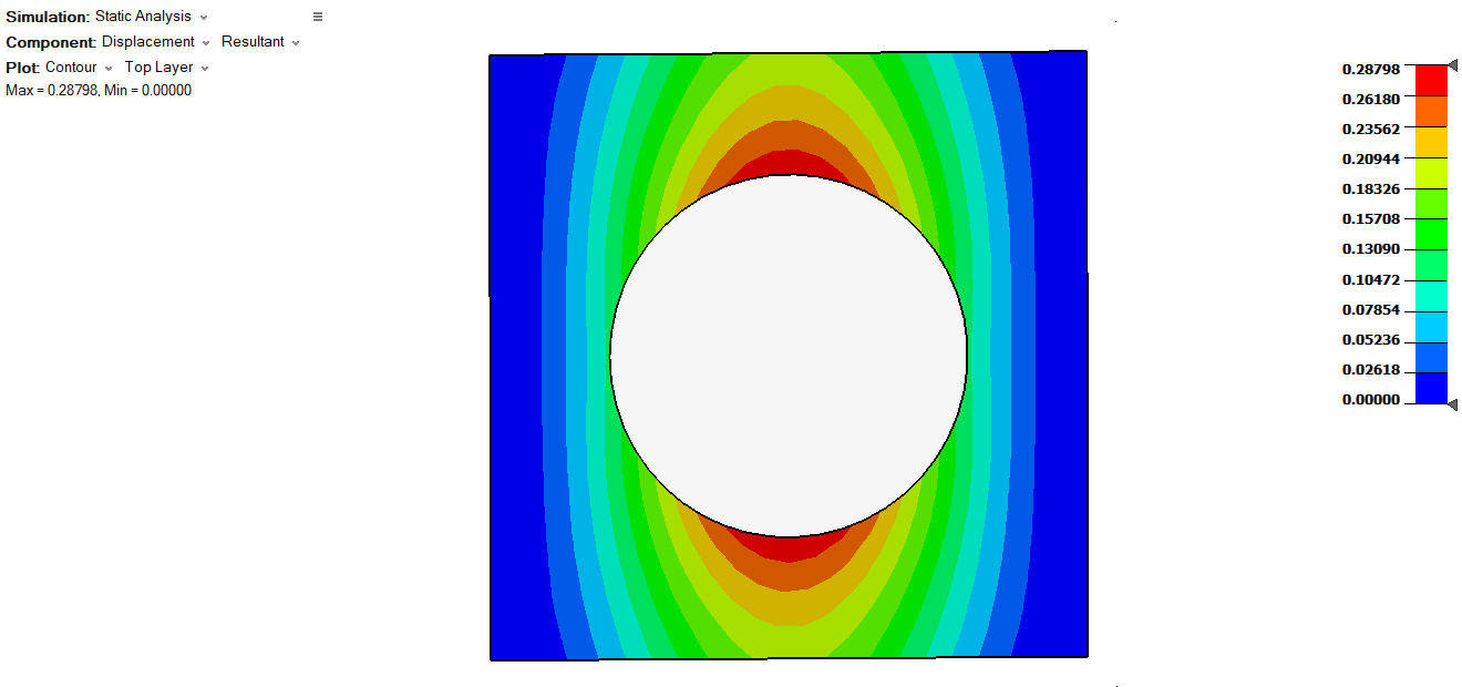
Figure 9. Example Stress Results (VonMises)