
OS-SL-T: 1020 Fatigue Analysis of a Universal Joint
Tutorial Level: Intermediate This tutorial demonstrates the creation of finite elements on a given CAD geometry of a universal joint.
Before you begin, copy the file(s) used in this tutorial to your
working directory.
The application of boundary conditions and a finite element analysis of the problem is explained. Post-processing tools are used to determine the fatigue life of the joint due to static loading.
The following exercises are included:
- Set up the problem in SimLab
- Apply Loads and Boundary Conditions
- Solve the job
- View the results
Launch SimLab
Launch SimLab.
Import the Model
-
From the menu bar, click .
An Import File dialog opens.
- Select the Universal_Joint.gda file you saved to your working directory from the Universal_Joint.zip file.
-
Click Open.
The Universal_Joint.zip database is loaded into SimLab. The .gda file only contains geometric data.
Create Solution
- From the Assembly tab of the Model Browser, select the Universal Joint and RBE bodies.
-
From the Solutions ribbon,
Physics group, click the
Structural tool.
The Create Solution dialog opens.
-
In the Create Solution dialog, define the following
options:
- For Name, enter Static Loading.
- For Solver, select OptiStruct.
- For Solution type, select Linear Static.
- Click OK.
Figure 1. Create Solution 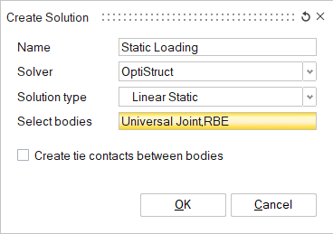
Create Materials and Properties
Create Material
-
From the Analysis ribbon,
Property group, click the
Material tool.
The Material dialog opens.
-
In the Material dialog, enter the values as shown below
and click OK.
Figure 2. Fatigue Material Creation 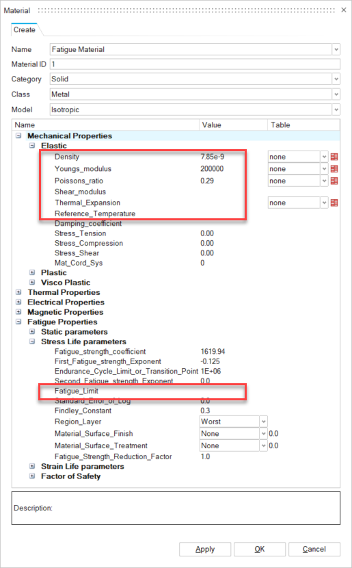
The Fatigue material is created in the Property tab of the Model Browser.
Create Property
-
From the Analysis ribbon,
Property group, click the
Property tool.
The Analysis Property dialog opens.
-
In the Analysis Property dialog, enter the values as shown
below.
Figure 3. Create Analysis Property 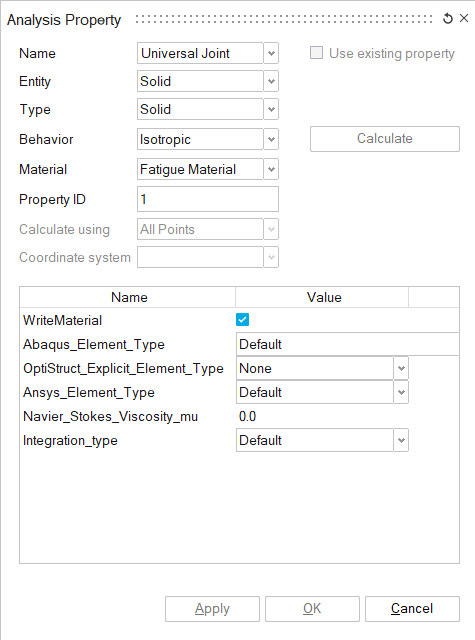
- In the Assembly tab of the Model Browser, select Universal Joint.
- In the Analysis Property dialog, click Apply.
-
Create a RBE property.
-
In the Analysis Property dialog, enter the values
as shown below.
Figure 4. Create RBE Property 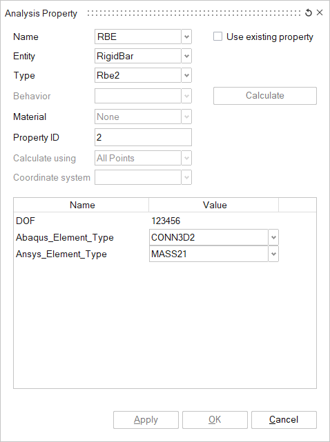
-
In the Analysis Property dialog, enter the values
as shown below.
Set Up Loads and Constraints
Define Torque Load
- From the Analysis ribbon, Loads and Constraints group, click the Loads tool.
-
From the secondary tool set, open the Force and Moment
tool.
The Force and Moment dialog opens.
-
In the modeling window, right-click and select
RBE Node from the context menu.
Figure 5. Select RBE Main Node Selection Filter 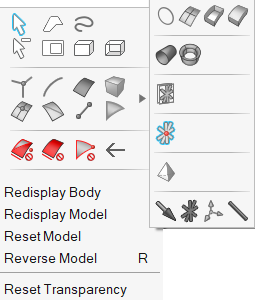
-
In the modeling window, select the RBE main node
attached to the Universal joint.
Figure 6. Select RBE Main Node 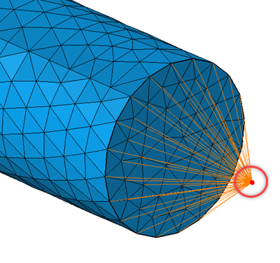
-
In the Force and Moment dialog, enter the values as shown
below and click OK.
Figure 7. Torque Load Creation 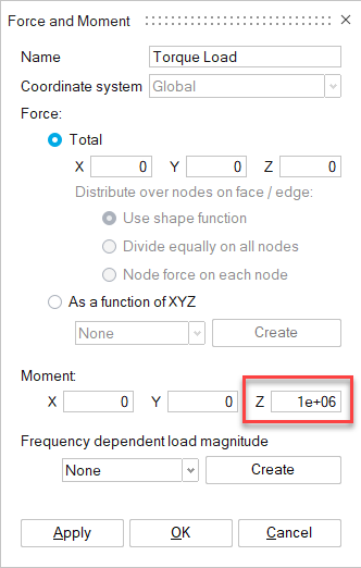
Define Constraints
- From the Analysis ribbon, Loads and Constraints group, click the Constraints tool.
-
From the secondary tool set, select the Fixed
tool.
The Fixed Constraint dialog opens.
-
In the Fixed Constraint dialog, enter the values as shown
below.
Figure 8. Create Fixed End Constraint 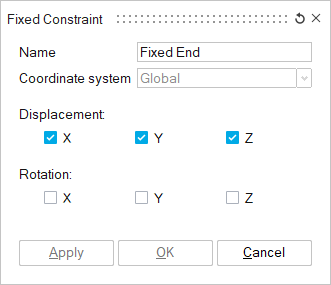
-
In the modeling window, select the faces of the
Universal Joint body.
Figure 9. Face Input for Fixed End Constraint 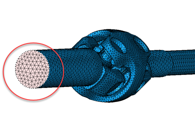
- In the Fixed Constraint dialog, click OK.
Define Fatigue Solution
-
From the Solutions ribbon,
Application group, click the
Fatigue tool.
The Fatigue dialog opens.
-
In the Fatigue dialog, enter the values as shown below and
click OK.
Figure 10. Set Fatigue Solution Parameters 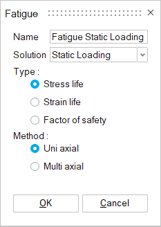
The Fatigue Solution is created in the Solution tab of the Model Browser. -
From the Analysis ribbon, Loads
group, click the Fatigue tool.
The Fatigue Loading dialog opens.
-
In the Fatigue Loading dialog, click
Apply.
Figure 11. Define Fatigue Loading 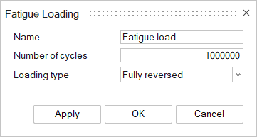
The fatigue loading is defined.
Solve and View Results
Solve the Solution
-
In the Solutions tab of the modeling window,
right-click on Results under the Static Loading solution
and select Update from the context menu.
The Solution begins to solve.
-
Right-click on Results under the Fatigue solution and
select Update from the context menu.
The solution begins to solve.
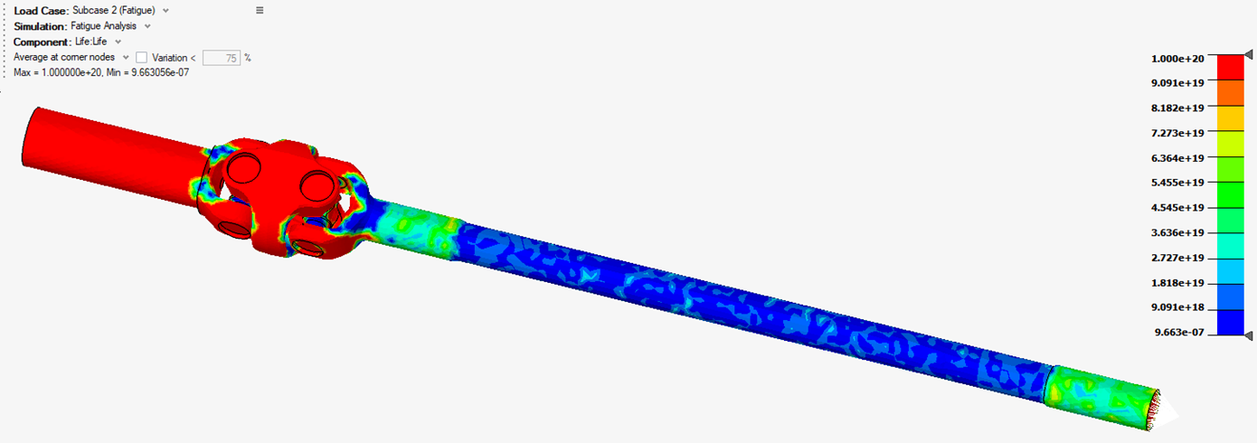
Interpret the Results
The results are automatically loaded in the modeling window.
-
Use the Results panel to change the result component.
Figure 13. Change Result Component 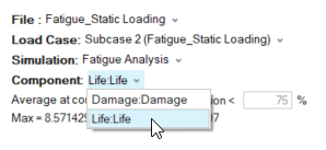
-
In the Solutions tab of the Model Browser, right-click
Results under the Static Loading solution and select
Display from the context menu.
Figure 14. Result Example 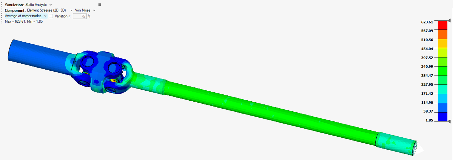
The results for the Static Loading solution are displayed.