OS-SL-T: 1030 Preloaded Modal Frequency Response Analysis
This tutorial demonstrates how to solve a modal frequency response analysis for a Differential housing model by including the effect of pretension of bolts as preload.
- Set up the problem in SimLab
- Apply Loads and Boundary Conditions
- Solve the job
- View the results
- Plot graph
Launch SimLab
Import the Model
Set Up Problem
Create Solid Bolds for Assembly
-
In the Create Solid Bolt dialog, enter the values as shown
below.
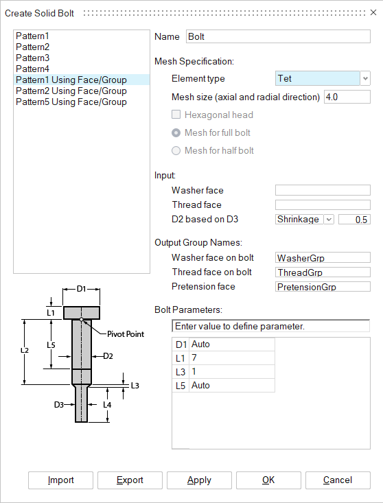
Figure 1. Bolt Parameters -
For Washer face Input, select the disc faces of the Cover body in the modeling window.
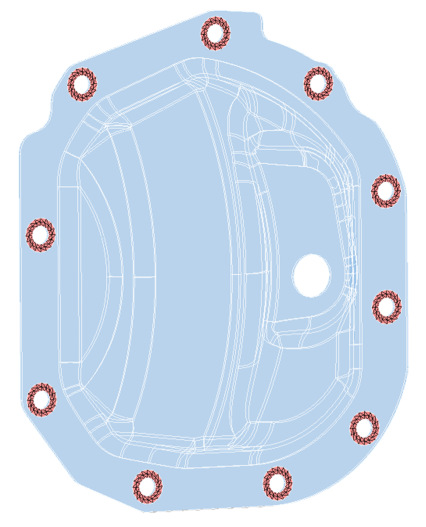
Figure 2. Select Disc Faces of Cover Body for Washer Face -
For Thread face Input, select the cylindrical faces of the carrier body in the
modeling window.
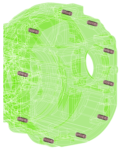
Figure 3. Select Cylindrical Faces of Carrier Body for Thread Face
Create Solution
-
In the Create Solution dialog, define the following
options:
-
For Select bodies, select all the bodies from the Assembly tab of the
Model Browser and click OK.
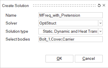
Figure 4. Create Solution
-
For Select bodies, select all the bodies from the Assembly tab of the
Model Browser and click OK.
Assign Property to Bodies
In this step you will assign the Cast Iron property for both the Carrier and Cover bodies and Steel property for the Bolts.
SimLab has default materials defined, so there is no need to define materials.
-
In the Analysis Property dialog, enter the values as shown
below and click Apply.
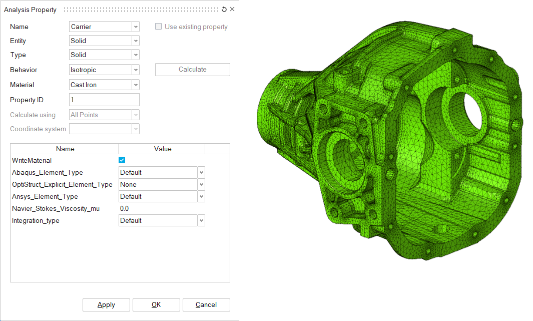
Figure 5. Carrier Body Property -
Create a property for the Cover body.
- In the modeling window, select the Cover body.
- In the Analysis Property dialog, enter the values as shown below and click Apply.
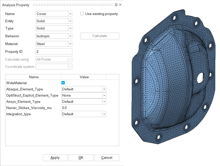
Figure 6. Cover Body Property -
Create a property for the Bolts.
- In the modeling window, select the Bolts.
- In the Analysis Property dialog, enter the values as shown below and click OK.
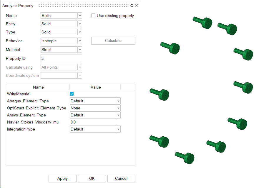
Figure 7. Bolts Property
Apply Loads and Boundary Conditions
The first loadcase is the non-linear static analysis where pretension is applied on the bolts and constraints are defined on the end of the carrier body. The second loadcase is the modal frequency response analysis in which a pressure load is applied on the inner face of the cover body and excitation load is created using the pressure load. The pretension effect of the bolts in the first loadcase is included in the second loadcase. Contacts are created between each part of the model.
Create Loadcase
Create Pretension Load
-
In the Create Solid Pretension dialog, enter the values as
shown below.
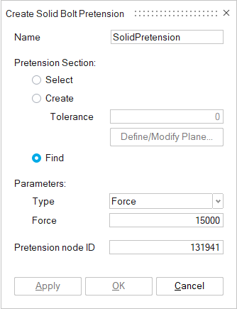
Figure 8. Create Solid Pretension for Bolts
Create Constraints
-
In the Fixed Constraint dialog, enter the values as shown
below.
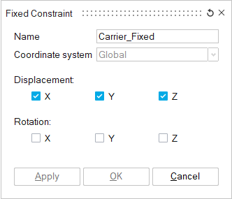
Figure 9. Fixed Constraint -
In the modeling window, select the cylindrical faces of
the Carrier body and click OK
in the Fixed Constraint dialog.
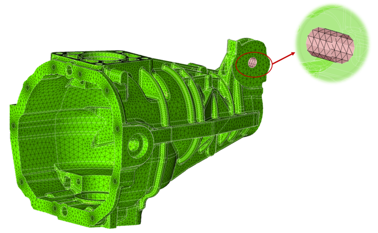
Figure 10. Select Fixed Constraint Faces
Define Loadcase Parameters
-
In the Loadcase Parameters dialog, enter the values as
shown below and click OK.
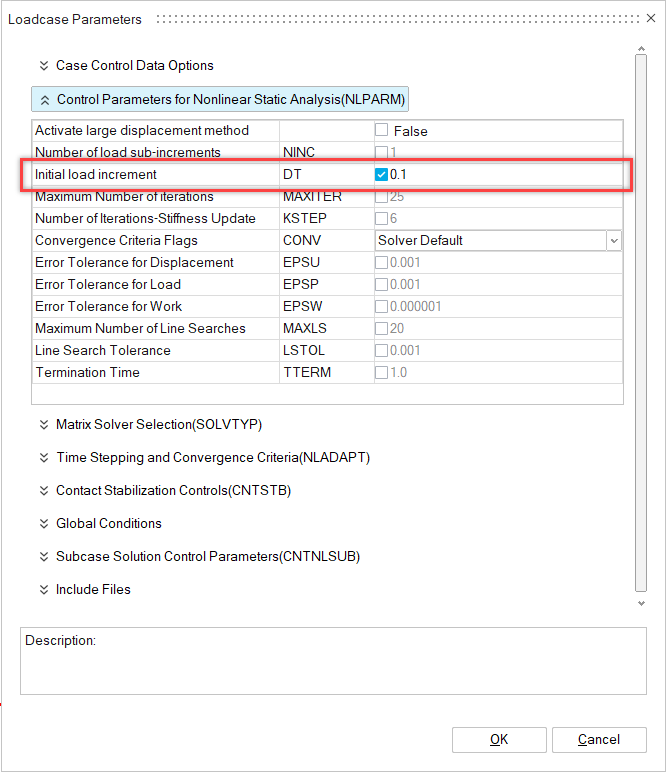
Figure 11. Loadcase Parameters Non Linear Analysis
Define Frequency Response Analysis Loadcase
Create Face Group for Pressure Load
Multiple faces must be selected to create a pressure load on the inner face of the cover body.
-
In the modeling window, select the face in the cover
body.
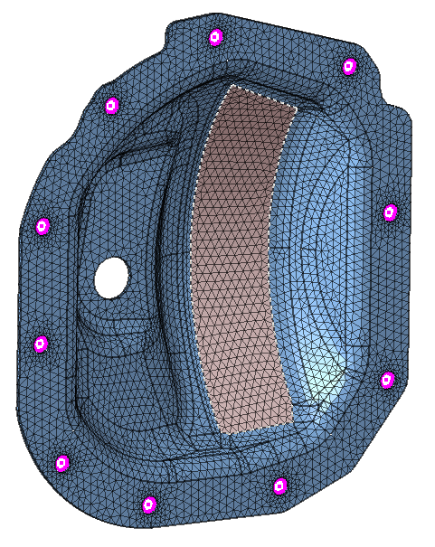
Figure 12. Select Face -
In the Select Adjacent Layers dialog, enable the
Create group checkbox and enter the name as
Pressure Faces.
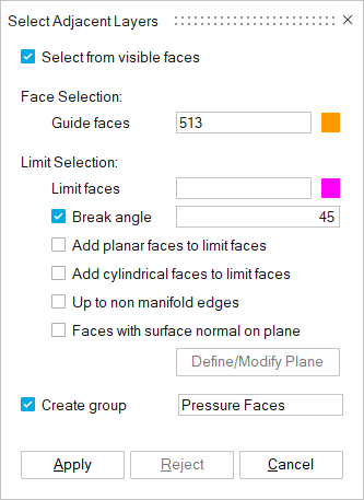
Figure 13. Create Group of Faces -
In the modeling window, select the limit faces and
click Apply in the
Select Adjacent Layers dialog.
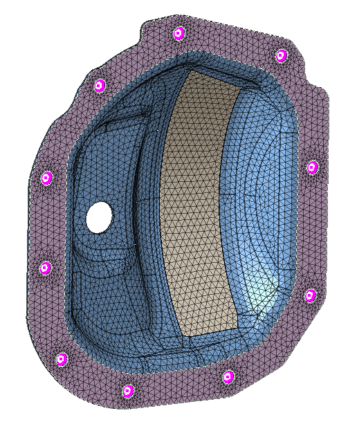
Figure 14. Select Limit Faces
Create Pressure Load
-
In the Pressure dialog, enter the values as shown
below.
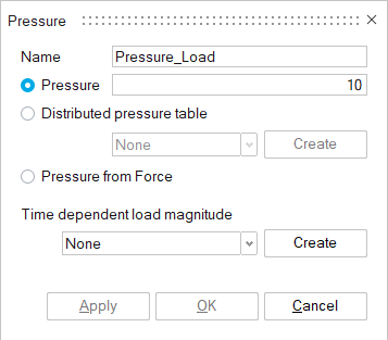
Figure 15. Pressure Load Input
Create Excitation Load
-
In the Create Table dialog, select
Frequency-Amplitude as the Loading Typer, enter the
values as shown below, and click OK.
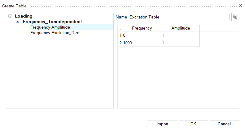
Figure 16. Define Amplitude Table for Excitation Load -
In the Excitation Load dialog, enter the values as shown
below and click OK.
The Pressure_Load defined will automatically be set as the Excitation load.
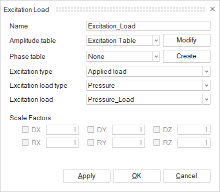
Figure 17. Excitation Load Input
Add Fixed Constraint
Define Loadcase Parameter and Result Request
-
In the Loadcase Parameters dialog, enter the values as
shown below and click OK.
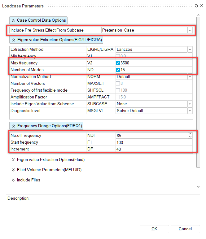
Figure 18. Loadcase Parameters Frequency Response Analysis -
In the Result Request dialog, enter the values as shown
below and click OK.
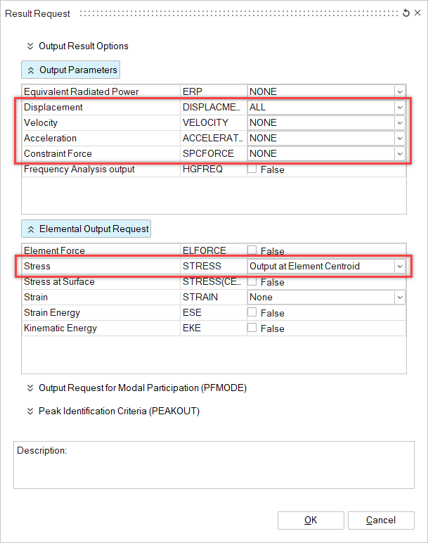
Figure 19. Result Requests for Frequency Response Analysis
Create Contacts
-
Create Cover_Bolts contact.
- In the Define Contact dialog, enter the values as shown below.
- In the modeling window, select the Cover for the main body and select the Bolts for the secondary body.
- In the Define Contact dialog, click Apply.
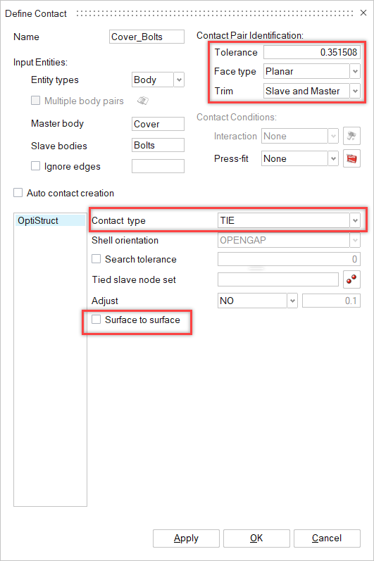
Figure 20. Contact Between Cover and Bolts -
Create Carrier_Bolts contact.
- In the Define Contact dialog, enter the values as shown below.
- In the modeling window, select the Carrier for the main body and select the Bolts for the secondary body.
- In the Define Contact dialog, click Apply.
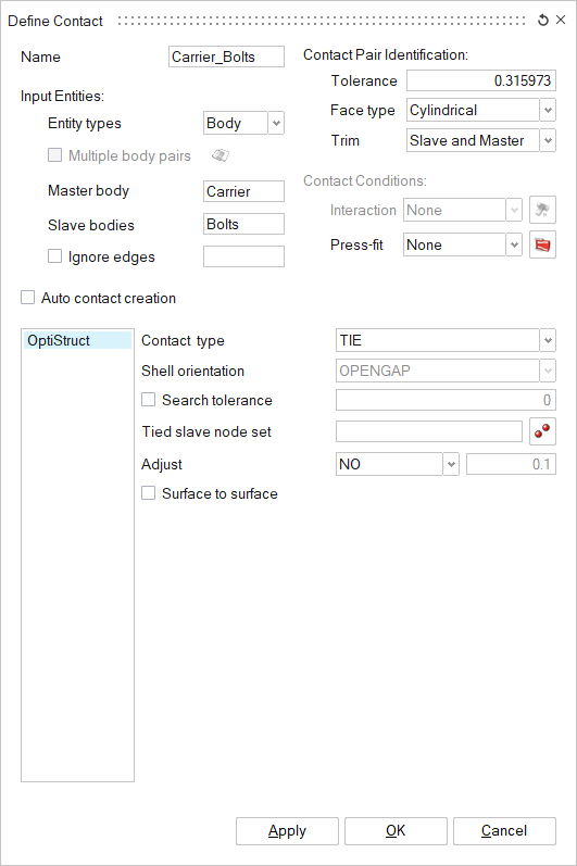
Figure 21. Contact Between Carrier and Bolts -
Create Cover_Carrier contact.
- In the Define Contact dialog, enter the values as shown below.
- In the modeling window, select the Cover for the main body and select the Carrier for the secondary body.
- In the Define Contact dialog, click OK.
This contact is created to prevent the overlapping of Carrier and Cover bodies.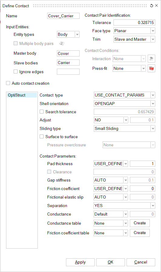
Figure 22. Contact Between Cover and Carrier
Solve and View Results
Solve the Solution
Interpret the Results
After the model setup has been successfully solved, the results are automatically appended to the input model.
-
In the Results panel, change the Load Case to view the
results of the Preloaded_MFreq loadcase.
The Simulation of Results panel lists all the frequencies for which the results are computed.
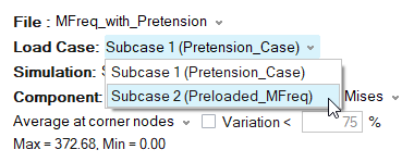
Figure 23. Change Loadcase
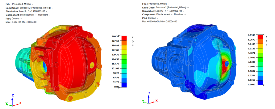
Figure 24. Example Displacement Results
Plot Graph
In this step you will plot a graph of resultant displacement at different frequencies of the Preloaded_MFreq subcase.
-
In the X Y Plot dialog, change the Data type to
Loadcase/Frequency.
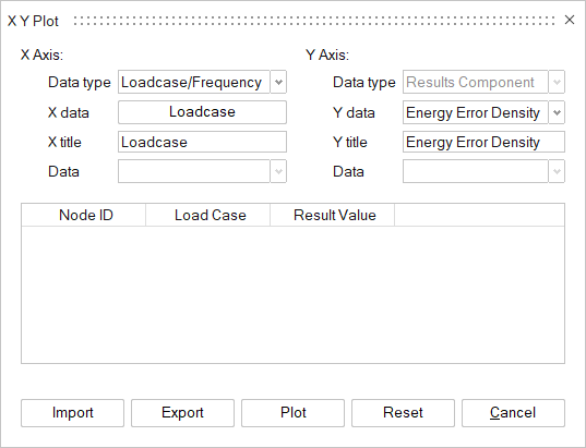
Figure 25. Change Data Type -
In the Loadcase dialog, enable the checkbox for
Subcase2 (Preloaded_MFreq) and click
OK.
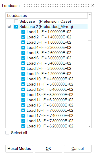
Figure 26. Select Subcase to Plot Graph -
In the modeling window, select any node from the model
and click Plot in the X Y Plot
dialog.
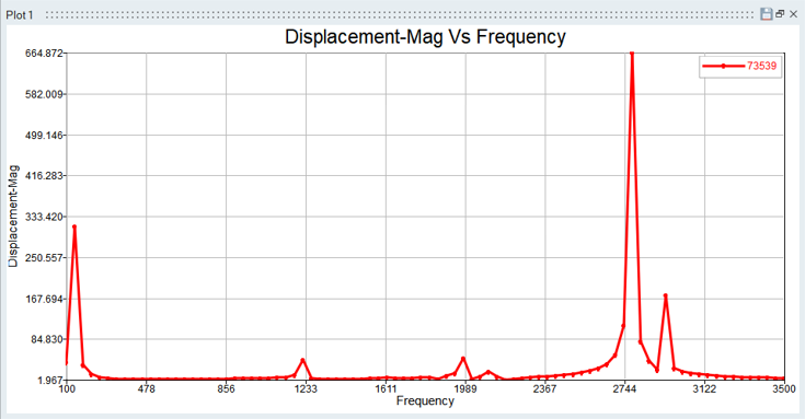
Figure 27. Example Graph