Application of boundary conditions and a finite element analysis of the problem are
explained. Post-processing tools are used to determine unstable modes produced
during braking.
The following exercises are included:
Set up the problem in SimLab
Apply Loads and Boundary Conditions
Solve the job
View the results
Launch SimLab
Launch SimLab.
Import the Model
From the menu bar, click File > Import > Database.
An Import File dialog opens.
Select the Brake_Model.gda file you saved to your
working directory from the Brake_Squeal.zip file.
Click Open.
The Brake_Model.gda database is loaded into
SimLab. The .gda file only
contains geometric data.
Create Solution
From the Solutions ribbon,
Physics group, click the
Structural tool.
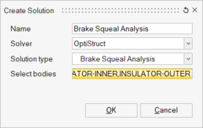
The Create Solution dialog opens.
In the Create Solution dialog, define the following
options:
For Name, enter Brake Squeal Analysis.
For Solver, select OptiStruct.
For Solution type, select Brake Squeal
Analysis.
For Select bodies, select all the bodies from the Assembly tab of the
Model Browser and click OK.
Figure 1. Solution Creation
In the Solutions tab of the Model Browser, an OptiStruct – Non Linear Static solution with the
selected bodies is created.
Create Materials and Properties
Create Material
From the Analysis ribbon,
Property group, click the
Material tool.
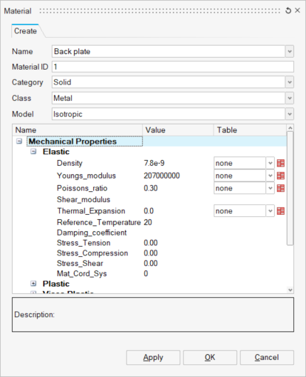
The Material dialog opens.
In the Material dialog, enter the values as shown below
and click Apply.
Figure 2. Back Plate Material Creation
The Back plate material is created in the Property tab of the Model Browser.
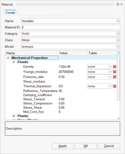
Create three more materials.
In the Material dialog, enter the values as shown
below and click Apply.
Figure 3. Create Insulator Material
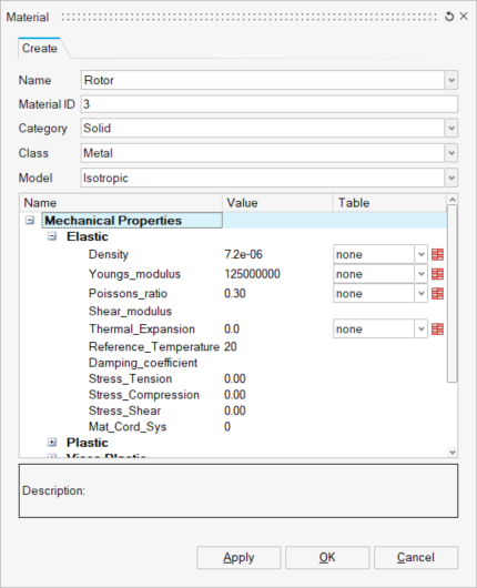
In the Material dialog, enter the values as shown
below and click Apply.
Figure 4. Create Rotor Material
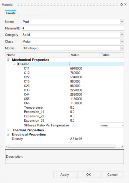
In the Material dialog, enter the values as shown
below and click OK.
Figure 5. Create Pad Material
The created materials are displayed in the Property tab of
the Model Browser.
Create Property
From the Analysis ribbon,
Property group, click the
Property tool.
The Analysis Property dialog opens.
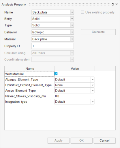
In the Analysis Property dialog, enter the values as shown
below.
Figure 6. Create Analysis Property
In the Assembly tab of the Model Browser, select
INNER-BACKPLATE and
OUTER-BACKPLATE.
Figure 7. Assign Property to Back Plate
In the Analysis Property dialog, click Apply.
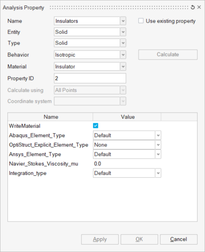
Create an Insulators property.
In the Analysis Property dialog, enter the values
as shown below.
Figure 8. Create Insulator Property
In the Assembly tab of the Model Browser,
select INSULATOR-INNER and
INSULATOR-OUTER.
In the Analysis Property dialog, click
Apply.
Create a Rotor property.
In the Analysis Property dialog, enter the values
as shown below.
Figure 9. Create Rotor Property
In the Assembly tab of the Model Browser,
select ROTOR.
In the Analysis Property dialog, click
Apply.
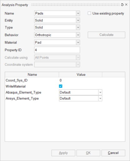
Create a Pad property.
In the Analysis Property dialog, enter the values
as shown below.
Figure 10. Create Pad Property
In the Assembly tab of the Model Browser,
select INNER-PAD and
OUTER-PAD.
In the Analysis Property dialog, click
Apply.
In the Analysis Property dialog, click
Cancel.
The created properties are displayed in the Property tab of
the Model Browser.
Set Up Loads and Constraints
Create Local Coordinate
From the Analysis ribbon, Loads and
Constraints group, click the Coordinate
tool.
From the secondary tool set, select the Create
tool.
The Create Coordinate System dialog
opens.
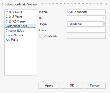
In the Create Coordinate System dialog, enter the values
as shown below.
Figure 11. Create Cylindrical Coordinate
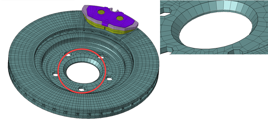
In the modeling window, select the cylindrical face
from the Rotor.
Figure 12. Face Input for Cylindrical Coordinate Creation
In the Create Coordinate System dialog, click
OK.
A cylindrical coordinate is created at the center of the
selected face. The coordinate is added in the Solutions tab of the Model Browser.
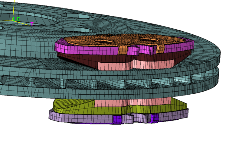
Create Contacts
Contacts are created between the Rotor and Pads to simulate the braking action of the
pads against the rotor.
From the Analysis ribbon, Loads and
Constraints group, click the Contact
tool.
The Define Contact dialog opens.
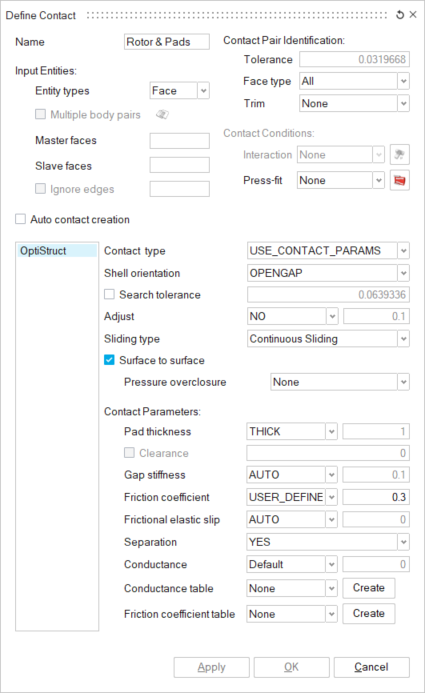
In the Define Contact dialog, enter the values as shown
below.
Figure 13. Create Contact
In the Define Contact dialog, select the line edit field
for Main faces.
The line edit field is highlighted.
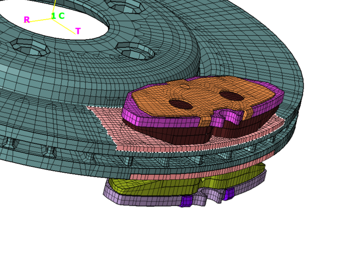
In the modeling window, select the Rotor
faces.
Figure 14. Main Face Inputs for Contact Creation
In the Define Contact dialog, select the line edit field
for Secondary faces.
The line edit field is highlighted.
In the modeling window, select the Pad
faces.
Figure 15. Secondary Face Inputs for Contact Creation
In the Define Contact dialog, select
Create for the Friction coefficient table
parameter.
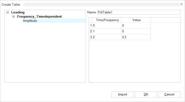
The Create Table dialog opens.
In the Create Table dialog, enter the values as shown
below and click OK.
Figure 16. Define Friction Co-Efficient Table
Tip: Press Enter
within the table cells to add additional rows.
In the Define Contact dialog, click OK.
The contact is created and added to the Solutions tab of the
Model Browser.
Create Loadcase
In the Solutions tab of the Model Browser, right-click
the Brake Squeal Analysis solution and select
Define using Load case from the context menu.
A loadcase is created and added in the Solutions tab of the Model Browser.
Right-click on LoadCase1, select
Rename from the context menu,
and enter Brake Pressure.
The Loads and Constraints pertaining to simulate the braking action of the
pads against the rotor are added in the Brake Pressure loadcase.
Create a Disc Rotation loadcase.
Right-click on LoadCase and selection Create
Loadcase from the context menu.
Right-click on the LoadCase2, select
Rename from the context menu, and enter Disc
Rotation.
Create a Brake Squeal loadcase.
Right-click on LoadCase and selection
Create Loadcase from the context menu.
Right-click on LoadCase3, select
Rename from the context menu, and enter Brake
Squeal.
Right-click on Type and selectAnalysis Type > Brake Squeal Analysis.
Define Brake Pressure
In the Solutions tab of the Model Browser, right-click
the Brake Pressure loadcase and select Set
Current from the context menu.
The Brake Pressure loadcase is set to current. All newly created loads
and constraints will be added to the current loadcase.
From the Analysis ribbon, Loads and
Constraints group, click the Loads
tool.
From the secondary tool set, select the Pressure
tool.
The Pressure dialog opens.
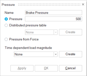
In the Pressure dialog, enter the values as shown
below.
Figure 17. Define Brake Pressure
In the modeling window, select the top faces of both
Insulators.
Figure 18. Face Inputs for Brake Pressure
In the Pressure dialog, click OK.
The Brake Pressure is added to the current loadcase in the
Solutions tab of the Model Browser.
Create Constraints
From the Analysis ribbon, Loads and
Constraints group, click the Constraints
tool.
From the secondary tool set, click the Fixed tool.
The Fixed Constraint dialog opens.
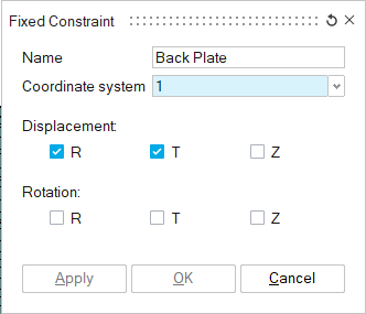
In the Fixed Constraint dialog, enter the values as shown
below.
Figure 19. Create Back Plate Constraint
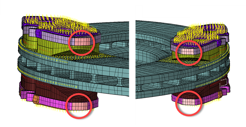
In the modeling window, select the side faces of both
back plates.
Figure 20. Face Input for Back Plate Constraint
In the Fixed Constraint dialog, click Apply.
The Back plate constraint is added to the current loadcase in the
Solutions tab of the Model Browser.
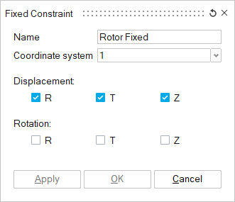
Create a Rotor Fixed constraint.
In the Fixed Constraint dialog, enter the values
as shown below.
Figure 21. Create Rotor Fixed Constraint
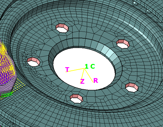
In the modeling window, select the faces at the
Bolt holes of the Rotor.
Figure 22. Face Input for Rotor Fixed Constraint
In the Fixed Constraint dialog, click
OK.
The Rotor Fixed constraint is added to the current loadcase in the
Solutions tab of the Model Browser.
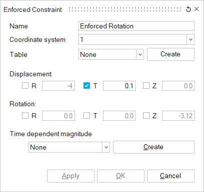
Define Enforced Displacement
The enforced displacement is used to simulate the rotation of the rotor against the
brake pads.
In the Solutions tab of the Model Browser, right-click
on the Disc Rotation loadcase and select Set
Current from the context menu.
Right-click on the Rotor Fixed constraint under the
Brake Pressure loadcase and select Add to current
Loadcase from the context menu.
The
Rotor Fixed constraint is added to the Disc Rotation loadcase.
Right-click on the Brake Pressure constraint under the
Brake Pressure loadcase and select Add to current
Loadcase from the context menu.
Right-click on the Back Plate constraint under the Brake
Pressure loadcase and select Add to current Loadcase from
the context menu.
From the Analysis ribbon, Loads and
Constraints group, click the Constraints
tool.
From the secondary tool set, click the Enforced
tool.
The Enforced Constraint dialog opens.
In the Enforced Constraint dialog, enter the values as
shown below.
Figure 23. Create Enforced Constraint
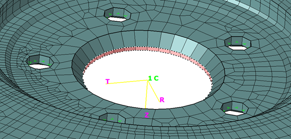
In the modeling window, select the cylindrical face at
the center of the rotor.
Figure 24. Face Input for Enforced Constraint
In the Enforced Constraint dialog, click
OK.
The Enforced Rotation is added to the Disc Rotation loadcase
in the Solutions tab of the Model Browser.
Define Brake Squeal Loadcase
In the Solutions tab of the Model Browser, right-click
on the Brake Squeal loadcase and select Set
Current from the context menu.
Right-click on the Rotor Fixed constraint under the Disc
Rotation loadcase and select Add to current Loadcase from
the context menu.
Right-click on the Back Plate constraint under the Disc
Rotation loadcase and select Add to current Loadcase from
the context menu.
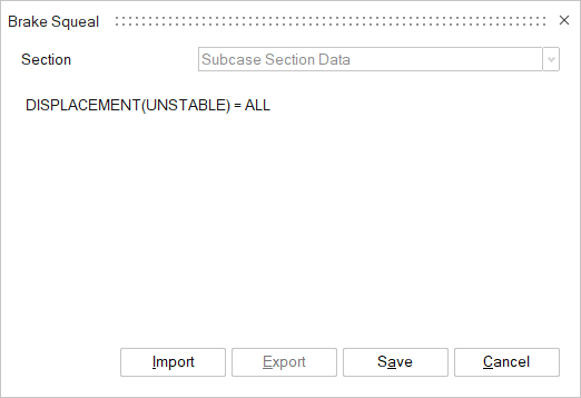
Right-click on the Brake Squeal loadcase and select
Text Data from the context menu.
In the Text Data dialog, enter
DISPLACEMENT(UNSTABLE) = ALL and click
Save.
Figure 25. Enter Text Data
Define Loadcase Parameters and Output Requests
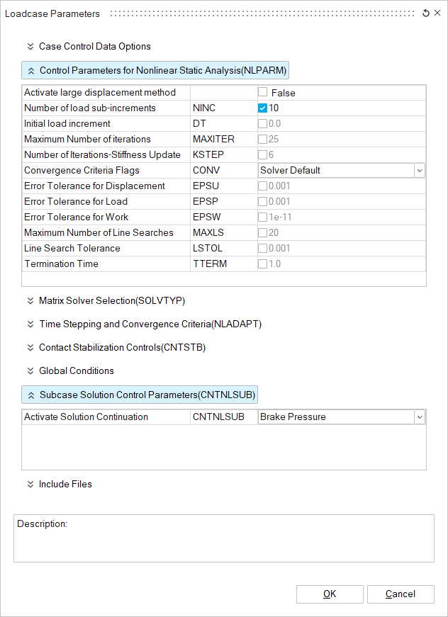
In the Solutions tab of the Model Browser, right-click
on the Brake Pressure loadcase and select
Loadcase Parameters from the context menu.
The Loadcase Parameters dialog opens.
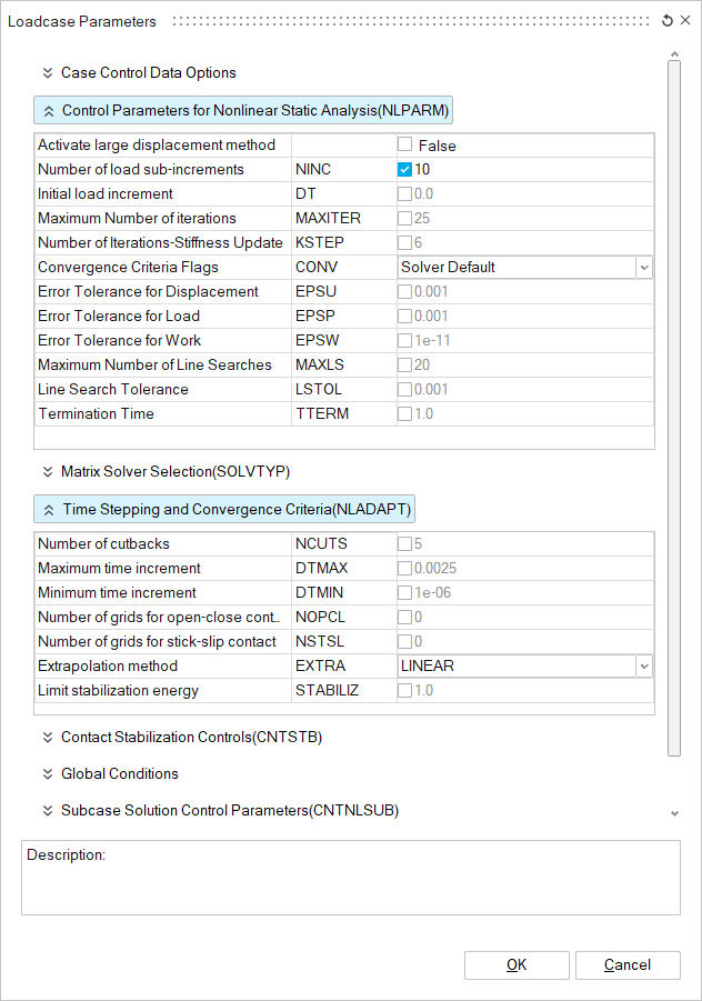
In the Loadcase Parameters dialog, enter the values as
shown below and click OK.
Figure 26. Create Loadcase Parameters for Brake Pressure
Loadcase
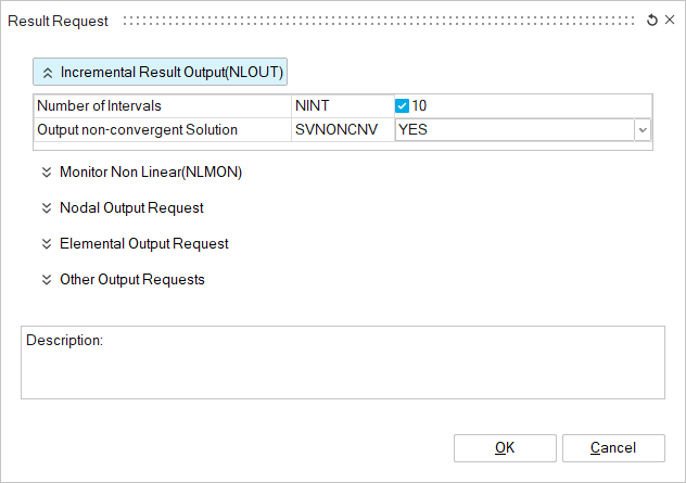
Right-click on the Brake Pressure loadcase, and select
Result Request from the context menu.
The Result Request dialog opens.
In the Result Request dialog, enter the values as shown
below and click OK.
Figure 27. Create Output Requests for Brake Pressure
Loadcase
Create loadcase parameters and output requests for the Disc Rotation
loadcase.
Right-click on the Disc Rotation loadcase and
select Loadcase Parameters from the context menu.
The Loadcase Parameters dialog
opens.
In the Loadcase Parameters dialog, enter the
values as shown below and click OK.
Figure 28. Create Loadcase Parameters for Disc Roation Loadcase
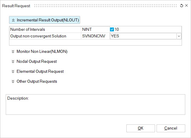
Right-click on the Disc Rotation loadcase, and
select Result Request from the context menu.
The Result Request dialog
opens.
In the Result Request dialog, enter the values as
shown below and click OK.
Figure 29. Create Output Requests for Disc Roation Loadcase
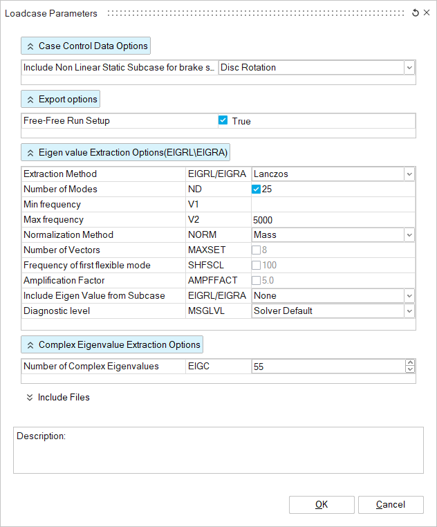
Create loadcase parameters for the Brake Squeal loadcase.
Right-click on the Brake Squeal loadcase and
select Loadcase Parameters from the context menu.
The Loadcase Parameters dialog
opens.
In the Loadcase Parameters dialog, enter the
values as shown below and click OK.
Figure 30. Create Loadcase Parameters for Brake Squeal Loadcase
The created loadcase parameters and output requests are
added in the Solutions tab of the Model Browser.
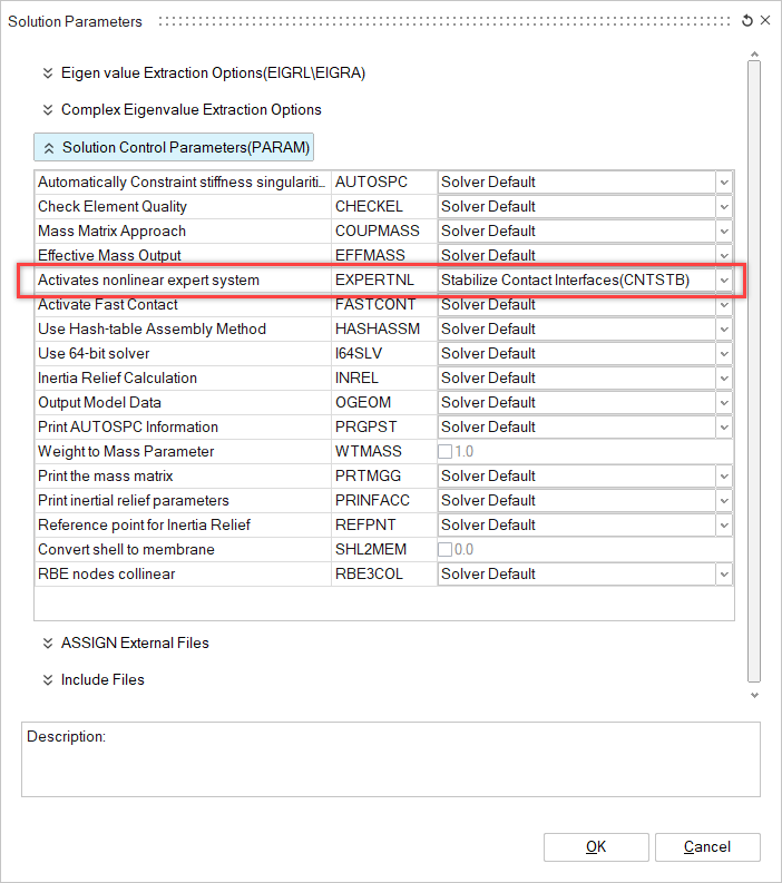
Create Solution Parameters
In the Solutions tab of the Model Browser, right-click
on the Brake Squeal Analysis solution and select
Solution Parameters from the context menu.
The Solution Parameters dialog opens.
In the Solution Parameters dialog, enter the values as
shown below and click OK.
Figure 31. Enter Solution Parameters Values
Solve and View Results
Solve the Solution
In the Solutions tab of the modeling window,
right-click on Results and select
Update from the context menu.
The Solution begins to solve.
The results are automatically loaded back into the
database.
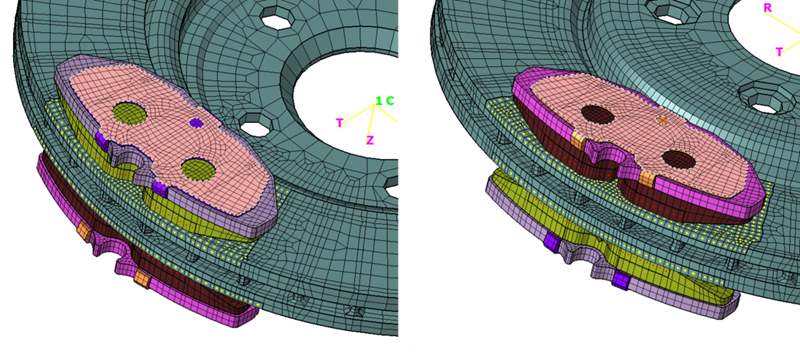
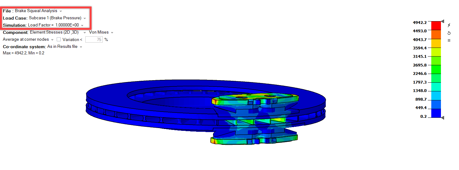
Interpret the Results
The results are automatically loaded in the modeling window.
By default, the results data for the first loadcase will be displayed. Use the
Results panel to change the loadcases, result component, and time steps. Figure 32. Results Loading After Solving
Animate the results using the Animation toolbar at the bottom of the modeling window.
In the Results panel, change the results loadcase from Brake Pressure to
Disc Rotation.
The stress developed due to the combined action of Disc roation and braking
can be inferred.
Change the results loadcase from Disc Rotation to Brake
Squeal.
In the Brake Squeal loadcase, three unstable modes (Mode 8, Mode 14, and Mode
22) are produced at frequencies of 1950.32 Hz, 3270.60 Hz, and 4776.90 Hz,
respectively.
Optional: From the Animation toolbar in the modeling window,
select XYZ Deformation to visualize the mode
shapes.