In the Create Sets window that opens, for Name enter
Residual.
For Card Image, select SET_ELEM from the drop-down menu.
For SET_TYPE, select non_ordered from the
drop-down.
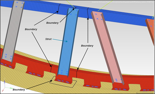
For Entity IDs, double-click on Elements and select the
elements inside the boundary as shown in Figure 2.
Figure 2. Residual Set Element Boundary
Click Close.
Note: The small patch of the elements attached to the
large RBE2 spider should be part of the superelement, not the residual
structure.
Create a Set for Boundary Nodes
From the menu bar, select the
Model ribbon.
On the Model ribbon, select Set.
Figure 3.
In the Create Sets window that opens, for Name enter
Aset.
For Card Image, select SET_GRID from the drop-down menu.
For SET_TYPE, select non_ordered from the
drop-down.
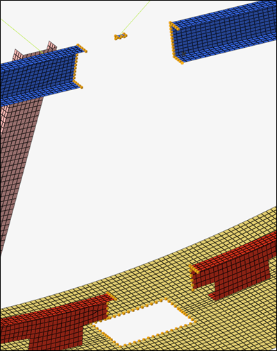
For Entity IDs, double-click on Nodes and select the
nodes on the boundary of the residual set element as shown in Figure 4.
Figure 4. Boundary Node Selection
Click Close.
Note: The boundary is approximate. It needs to be a few
elements away from the connections.
Save the model.
From the menu bar, select File > Save As > HyperMesh Model.
For Name, enter airframe_section_CMS.hm.
Sets created for the superelements and residual are useful for the remainder
of the tutorial. The model must be recovered from this point in future
steps.
Create ASET Constraints
In the Model Browser, right-click and select
Create > Load Collector.
A new Create Load Collector window
opens.
For Name, enter Aset.
Click Color and
select a color from the color palette.
For Card Image, verify none is selected.
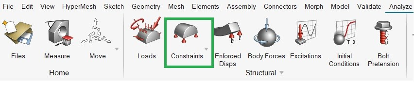
On the menu bar, select
Analyze.
On the Analyze ribbon, Select Constraints.
Figure 5. A new panel for constraints opens.
On the panel, for load types select ASET.
Select all six degrees of freedom.
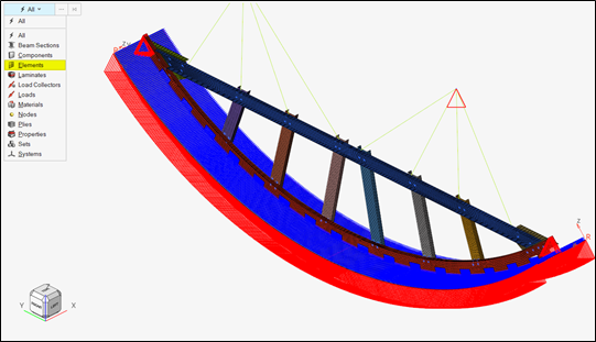
For nodes, select to open Advanced Selection.
In the dialog, select by sets and use the
ASET nodal set as shown in Figure 6.
Figure 6. Constraint Load Collector for ASET Load Type
Click Create.
Click close.
Delete Residual Set Element
The reduced stiffness and mass matrix are generated for only those elements that are
reduced out (superelement). Therefore, a new model needs to be created containing
just the superelement part and the loads and boundary conditions applied directly to
that part.
On the guide bar, Select Entity drop-down menu, select
Elements.
Click to open Advanced Selection.
Figure 7. Select Entity Menu
Note: You can also press the Spacebar
to open Advanced Selection.
In the Advanced Selection window, choose selection By
Set from the drop-down menu.
Choose the Residual set element.
Click OK.
On the guide bar, right-click the Select
Entity menu and choose Delete from the
context menu.
The element related to the residual set is deleted.
Optional: Alternatively, you can delete the residual set using panels.
Select the Tool panel radio button.
On the panel, select delete > Elements.
Select element deletion by set > Residual.
Select delete entity.
Delete the empty Residual set that comprises the
residual structure.
If the set is not deleted, an error appears.
Define CMS Method Entry
The CMSMETH load collector triggers the creation of the reduced
matrices.
In the Model Browser, right-click and select
Create > Load Collector.
A new Create Load Collector window
opens.
For Name, enter CMSMETH.
Click Color and
select a color from the color palette.
For Card Image, select CMSMETH.
For Type, select Structure only from the drop-down
menu.
For METHOD, select CBN from the drop-down menu.
For NMODES (number of normal modes), enter 10.
Select the SPID_INT check box.
For SPID, enter 999999.
The starting SPOINT ID is used in DMIG matrix output for the structural
eigenmodes to define scalar points to which no scalar elements are
connected.
Click Close.
Run the CMSMETH Global Case Control
On the Analyze ribbon, under the Analyze tool group, select Run > Global Case Control.
Click Unspecified and select to open the Advanced Selection
dialog.
In the dialog, select the CMSMETHOD load
collector.
Click OK.
Click Close.
Note:The GLOBAL_CASE_CONTROL Bulk Data
Entry is required to activate the matrix save the process. Without this
parameter, the run proceeds as normal.
Save the Model
Save as a new model.
Click File > Save as > HyperMesh Model.
For File name, enter
airframe_section_SUPERELEMENT_CMS.hm.
Click Save.
Delete the Normal Modes Load Step
In the Model Browser, double-click Load
Steps.
In the Load Steps browser tab, right-click on the
NormalModes load step and select
Delete from the context menu.
The CMS method automatically triggers the normal mode analysis. If not
deleted it triggers an error.
Run Superelement Generation
On the Analyze ribbon, under the Analyze tool group, select Run
OptiStruct Solver.
The panel area opens.
Click Save as.
For File name, enter
airframe_section_SUPERELEMENT_CMS.fem.
The .fem extension is necessary to recognize this as an
input file.
Click Save.
Set export options: to all.
Set run options: to analysis.
Click Run.
If the job was successful, new results files appear in the directory
where Altair HyperWorks was invoked. The
airframe_section_SUPERELEMENT_CMS.out file is a good
place to look for error messages to help debug the input deck if any errors are
present.


 to open Advanced Selection.

 .
The panel area opens.
.
The panel area opens.