The structure of a system definition is similar to an MDL model file, so you can
reuse the pendulum model file from the other tutorial to generate a more generalized
system definition.
Copy the pendulum.mdl file, located in the
mbd_modeling\mdl folder, to your <working
directory>.
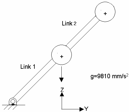
Below is a sample MDL file for the pendulum model in the previous
tutorial:
You
can convert the MDL file into a system definition by making small changes to the
MDL file.
Important: This conversion is not applicable in all cases.
You will need to take care of some conditions (which will be described later
in the tutorial).
Replace the *BeginMDL() and *EndMDL()
statements with the *DefineSystem() and
*EndDefine() statements, respectively. Specify an
appropriate variable name for the system definition.
Use the statements att_point and att_body to
specify where the system connects (attachment point or pivot point) and to what
body it connects (attachment body).
Use these variables in the *DefineSystem() statement.
Note:
As mentioned earlier, the attachment entity can be any MDL entity. Therefore
you must specify the entity type that the variable represents (for example,
att_point represents the POINT entity).
Use the *Attachment() statement to specify the entity type
that each variable represents:
*Attachment (att_point, "Pivot Point", POINT, "Attachment point where
the pendulum definition gets attached")
*Attachment (att_body, "Attachment body" , BODY, " Any body to which the
pendulum definition gets attached")
Note: In the original model variable p_pendu_pivot represented
the pivot point. While converting the pendulum model to pendulum system
definition, this pivot point would be provided by the attachment
point.
The point p_pendu_pivot is now passed as an attachment,
therefore we do not need to define the pivot point.
Delete the statement *Point (p_pendu_pivot, "Pivot
Point").
Retain the pendulum CM point, as well as the *Body()
statement.
In the *RevJoint() statement, replace
B_ground with att_body and replace
p_pendu_pivot with att_point.
Retain the sphere *Graphic() statement.
In the cylinder *Graphic() statement, replace the variable
p_pendu_pivot with att_point.
Note: Throughout the script, wherever applicable, the attachment variables
should replace the original variables.
Retain the *Output() statement.
This allows you to obtain displacement outputs on each pendulum body in
the model.
Remove *setpoint (p_pendu_pivot, 0, 5, 5).
In the *Setpoint() statement, parameterize the points in the
system using the statement (att_point.y+5, att_point.z+5)
This will set the CM point 5 units away from the attachment
point.
Note: Below is a sample system definition (system.mdl):
// system.mdl
// created on:
*DefineSystem(sys_def_pendulum, att_point, att_body)
//Topology Data
// Declaration of Entities
//Attachments
*Attachment (att_point, "Pivot Point", Point, "Attachment
point where the pendulum definition gets attached")
*Attachment (att_body, "Attachment body" , Body, " Any body
to which the pendulum definition gets attached")
//Points
*Point( p_pendu_cm, "Pendulum CM")
//Bodies
*Body(b_link, "Ball", p_pendu_cm)
//Joints
*RevJoint(j_joint, "New Joint", att_body, b_link, att_point,
VECTOR, V_Global_X)
//Output
*Output(o_pendu, "Disp Output", DISP, BODY, b_link)
//Graphics
*Graphic(gr_sphere, "pendulum sphere graphic", SPHERE,
b_link, p_pendu_cm, 1 )
*Graphic(gr_link, "pendulum link graphic", CYLINDER, b_link,
att_point, POINT, p_pendu_cm, 0.5, CAPBOTH )
// Property Data
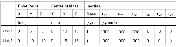
*SetPoint(p_pendu_cm, 0, att_point.y+5, att_point.z+5)
*SetBody(b_link, 1, 1000, 1000, 1000, 0, 0, 0)
*EndDefine()
Save the file as sys_pendu.mdl.
Add A System Definition by Manually Authoring your MDL File
In this step you will write an MDL file that includes the system definition and
instantiate it multiple times.
In a text editor, create a new empty file.
Begin the model file with the *BeginMDL() statement.
From the sys_pendu.mdl file, copy the text from
*DefineSystem() to *EndDefine() into the
new file under the *BeginMDL() statement.
Use the *System() statement to instantiate the first
pendulum system:
Note: You can also refer to the MDL
Language Reference online help for syntax.
Remember: When you instantiate the system, make sure to do the
following:
In the *System() statement, reference the system
definition by specifying its variable name as the third argument.
Use the same variable name for the system definition as you
specified in the corresponding *DefineSystem()
statement. In the above example, system1 uses the system definition
sys_def_pendulum.
If applicable, resolve any attachments in the system definition. For
example, sys_def_pendulum has an attachment,
att_body, to reference body_2
in the *RevJoint() statement. In
system1, the pendulum body,
b_link, should be connected to the ground body,
B_Ground. Therefore, B_Ground
is specified as the attachment body in the
*System() statement.
It is recommended that you add the *System()
statement before *DefineSystem(), although it is
not mandatory.
Repeat step 4
(with appropriate modifications) to create the second pendulum system.
Provide a different variable name, system2, for
the system instance.
Use Pendulum CM (p_pendu_cm) and the Pendulum Body
(b_link) from the first system as the
attachment.
The exact statement you should use is shown below:
*BeginMDL(model, "MODEL")
*System(system1, "First Pendulum System", sys_def_pendulum,
                        P_Global_Origin, B_Ground)
*System(system2, "Second Pendulum System", sys_def_pendulum,
system1.p_pendu_cm, system1.b_link )
*DefineSystem(sys_def_pendulum, att_point, att_body)
//Topology Data
// Declaration of Entities
//Attachments
*Attachment (att_point, "Pivot Point", Point, "Attachment point
where the pendulum definition gets attached")
*Attachment (att_body, "Attachment body" , Body, " Any body to which
the pendulum definition gets attached")
//Points
*Point( p_pendu_cm, "Pendulum CM")
//Bodies
*Body(b_link, "Pendulum Body", p_pendu_cm)
//Joints
*RevJoint(j_pivot, " Revolute Joint at Pivot Point ", b_link,
att_body, att_point, VECTOR, V_Global_X)
//Output
*Output(o_pendu, "Disp Output", DISP, BODY, b_link)
//Graphics
*Graphic(gr_sphere, "pendulum sphere graphic", SPHERE, b_link,
p_pendu_cm, 1 )
*Graphic(gr_link, "pendulum link graphic", CYLINDER, b_link,
att_point, POINT, p_pendu_cm, 0.5, CAPBOTH )
// Property Data
*SetPoint(p_pendu_cm, 0, att_point.y+5, att_point.z+5)
*SetBody(b_link, 1, 1000, 1000, 1000, 0, 0, 0)
*EndDefine()
*EndMDL()
Save the model as doublependulum.mdl.
Open the MDL file in MotionView. Review the model,
focusing particularly on the First Pendulum System and Second Pendulum System
files listed in the Project Browser.
Under the (System) icon, you will notice a small 'hand'
symbol. This indicates a feature known as Shared Definition, where both systems
have a single definition. Figure 3. When a system definition is shared, any modification to one instance can
be made to reflect all instances.
Make modifications to all instances.
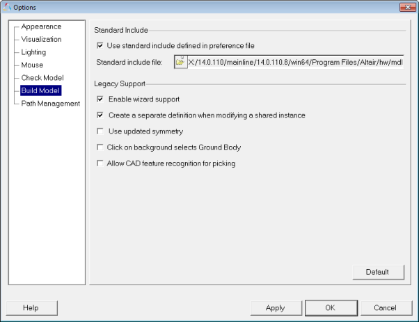
In the menu bar, click Tools > Options.
In the Options dialog, click Build Model
(located near the bottom of the tree).
Figure 4.
Under Legacy Support, uncheck the Create separate
definitions when modifying a shared instance
option.
Now when you make modifications to an instance, the change will
be applied across all instances without creating a separate
definition.
Click OK.
Run the MotionSolve simulation and post-process the
results.
Click the (Run) panel
button.
In the panel, specify an End time of 1.0 and a
Print interval of 0.01.

 (System) icon, you will notice a small 'hand'
symbol. This indicates a feature known as Shared Definition, where both systems
have a single definition.
(System) icon, you will notice a small 'hand'
symbol. This indicates a feature known as Shared Definition, where both systems
have a single definition. 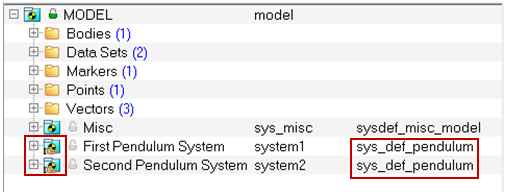
 (Run) panel
button.
(Run) panel
button.