MV-1060: Build a Pendulum Model Using MDL Statements
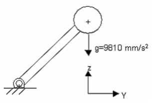
Tutorial Level: Beginner In this tutorial, you will learn how to create a pendulum model using Model Definition Language (MDL), run a dynamic simulation of the model, plot the rotation of the pendulum and view the animation.
- You can open and edit in any text editor.
- It assists with model debugging.
- You can use conditional statements "if" for custom modeling requirements.
- You can build modular and reusable models.
- You can parameterize the models.
- You can use modeling entities which are not available through GUI (for example, CommandSets).
- Section 1: Entities in MDL
- A modeling entity is saved to MDL in the form of MDL statements. All MDL
statements begin with an asterisk (*). There are two types of entities:
- General Entities
- Definition Based Entities
- General Entities
-
- Have one statement to define the entity. They may have one or more statements to set their properties.
- Some examples include points, bodies, joints, etc.
- Each general entity has certain properties consistent with its type. For example, a point has the properties x-coordinate, y-coordinate, z-coordinate, label, state, and varname (variable name).
- Definition Based Entities
-
- Are defined through a block statement, called definition, and its instance is created in a model by an instantiation statement.
- The block generally begins with a *Define() statement and end with a *EndDefine() statement.
- The entity (or block) is comprised of a series of other MDL entities or members.
- These entities are reusable. Once defined, the same entity-definition may be instantiated several times within the same model or different model files.
- Section 2: Properties of Entities
-
- Each entity has variable, label, and other properties associated with it.
- Each entity should have a unique variable name.
- Following is the recommended convention for variable names which allows the user to identify the modeling entity during debugging. You are not restricted to this nomenclature, however you are encouraged to adopt it.
- Section 3: Global Variables
- MotionView comes with Global Variables, by
default, which are available for use anywhere in the model. These variables
are case sensitive. The table below lists some commonly used keywords and what they represent:
Table 3. Common keywords in MotionView B_GroundGround body P_Global_OriginGlobal Origin V_Global_X, V_Global_Y, V_Global_ZVectors along the global XYZ axes Global_FrameGlobal reference marker MODELReference to the top level system of the model. - Section 4: MDL Statement Classification
-
- Topology Statements
- These are statements that define an entity and establish
topological relation between one entity and the other. For
example,
*Body(b_body, “Body”, p_cg). In this example, the *Body statement defines a body having its CG at pointp_cg. Through this statement the body (b_body) is topologically connected to pointp_cg. - Property or Set Statements
- These statements assign properties to the entities created by topological entities. For example, *SetBody() is a property statement that assign mass and inertia properties to a body defined using *Body(). Since most of the property statements begin with “*Set”, they are generally referred as Set statements.
- Definition and Data
- Building upon the concept of a definition block, these
terminologies are used specifically with regard to container
entities such as Systems, Assembly, and Analysis.The block of statements when contained within a *Define() block are termed as a Definition. The statements within the block may include:
- Topology statements that define entities.
- Set statements that assign properties. These Set statements within a definition block are called "Default Sets", as they are considered as default values for the entities in the definition.
Any statements or block that resides outside the context of *Define() block are termed as Data. These include:- Set statements within a *BeginContext() block that relate to entities within a system, assembly, or analysis definition.
- Some of the *Begin statements, such as *BeginAssemblySelection and *BeginAnalysis.
- Section 5: MDL Model File Overview
-
- MDL model file is an ASCII file; it can be edited using any text editor.
- All statements in a model are contained within a *BeginMDL() - *EndMDL() block.
- The syntax of the MDL statement is an asterisk (*) followed by a valid statement with its arguments defined.
- Statements without a leading asterisk (*) are considered comments. In this tutorial, comment statements are preceded by // to improve readability. The comments are not read in by the MotionView graphical user interface and are removed if the model MDL is saved back or saved to a different file.
MDL accepts statements in any order, with a few exceptions.
To help you learn this language, the code in the tutorial examples will follow this structure://comments about the MDL file *BeginMDL(argument list) //Topology section *Point… *Body… *System(…) // definitions sub-section *DefineSystem(..)… .. .*EndDefine() //Property of entities directly in *BeginMDL()//Property section for entities within Systems and analysis *BeginContext() .. .. *EndContext() . *EndMDL

Create an MDL Model File
In this step you will create an MDL model file for the pendulum model.
- Open a text editor.
-
Create comment statements describing the purpose of the model:
//Pendulum falling under gravity //date -
Create a *BeginMdl() - *EndMdl() block to signify the
beginning and the end of the model file.
Important: All other MDL model file statements should be between these block statements.This is the syntax for the *BegingMdl() statement:
*BeginMdl(model_name, "model_label")model_nameis the variable name of the model.model_labelis the descriptive model of the label.For the purpose of this tutorial, you will use:*BeginMdl(pendulum, "Pendulum Model") *EndMdl()Tip: Look for the syntax of the corresponding statements by navigating to the menu bar and clicking . Then type the statement in the Index. In MDL statements, only keywords are case-sensitive.
Create Entity Declarations
Here, you will create the entity declarations necessary for the problem.
-
Use the *Point() statement to create a point for the
pendulum pivot:
//Points
*Point(p_pendu_pivot, "Pivot Point")
The syntax of the *Point() statement is *Point(point_name, "point_label", [point_num]).point_nameThe variable name of the point (p_pendu_pivot).point_labelThe descriptive name of the point (Pivot Point).point_numAn optional integer argument assigned to the point as its identity number. You will not use one for this tutorial.
-
Use the *Point() statement to create a point for the
pendulum center of mass:
*Point(p_pendu_cm, "Pendulum CM")
-
Use the *Body() statement to define the ball’s body:
//Bodies
*Body(b_link, "Ball", p_pendu_cm)
The syntax for the *Body() statement is *Body(body_name, "body_label", [cm_origin], [im_origin], [lprf_origin],[body_num]).body_nameThe variable name of the body (b_link)body_labelThe descriptive label of the body that appears in the graphical display (Ball).cm_originAn optional argument for the origin point of the inertia marker of the body (p_pendu_cm).im_originAn optional argument for the origin point of the inertia marker of the body (not used in this model).lprf_originAn optional argument for the origin point of the local part reference frame of the body (not used in this model).body_numAn optional integer argument assigned to the body as its entity number (not used in this model).
[]in the description of any statement syntax indicate an argument is optional. -
Use the *Graphics() statement (one for cylinder and one for
sphere) to display the link and the sphere:
//Graphics
*Graphic(gr_link, "pendulum link graphic", CYLINDER, b_link
p_pendu_pivot, POINT, p_pendu_cm, 0.5, CAPBOTH )
*Graphic(gr_sphere, "pendulum sphere graphic", SPHERE, b_link,
p_pendu_cm, 1)
The syntax for the sphere graphic is *Graphic(gr_name, "gr_label", SPHERE, body, origin, radius).gr_nameThe variable name of the graphic (gr_sphere).gr_labelThe descriptive label of the graphic (pendulum sphere graphic)SPHEREThis argument indicates that the graphic is a sphere.bodyThe body associated with the graphic (b_link).originThe location of center point of the sphere (p_pendu_cm).radiusThe radius of the sphere (1).
The syntax for the cylinder graphic is *Graphic(gr_name, "gr_label", CYLINDER, body, point_1, POINT|VECTOR, orient_entity, radius, [CAPBOTH|CAPBEGIN|CAPEND]).gr_nameThe variable name of the graphic (gr_link).gr_labelThe descriptive label of the graphic (pendulum link graphic).CYLINDERThis argument indicates the graphic is a cylinder.bodyThe body associated with the graphic (b_link).Point 1The location of one end of the cylinder (p_pendu_pivot).POINT|VECTORKeyword to indicate the type of entity used to orient the cylinder. IfPOINTis used, the following argument should resolve to a point, otherwise it should resolve to a vector.orient_entityThe variable name of the entity for orienting the cylinder (p_pendu_cm).radiusThe radius of the cylinder (0.5).[CAPBOTH|CAPBEGIN|CAPEND]An optional argument that identifies if either or both cylinder ends should be capped (closed).
-
Use the *RevJoint() statement to create a revolute joint at
the pivot point:
The syntax for the *RevJoint() statement is *RevJoint(joint_name, "joint_label", body_1,body_2, origin, POINT|VECTOR, point|vector, [ALLOW_COMPLIANCE])//Revolute Joint *RevJoint(j_joint, "New Joint", B_Ground, b_link, p_pendu_pivot, VECTOR, V_Global_X)joint_nameThe variable name of the joint (j_joint).joint labelThe descriptive label of the revolute joint (New Joint).body 1The first body constrained by the revolute joint (B_ground).body 2The second body constrained by the revolute joint (b_link).originThe locations of revolute joint (p_pendu_pivot).POINT|VECTORKeyword to suggest the method of orientation for the joint using a point or vector (VECTOR).point|vectorA point or vector that defines the rotational axis of the revolute joint (V_Global_X).[ALLOW COMPLIANCE]An optional argument that indicates the joint can be made compliant (a joint that is compliant is treated like a bushing and can be toggled between compliant and non-compliant).
-
Use the *Output - output on entities statement to create an
entity output statement:
//Output
*Output(o_pendu, "Disp Output", DISP, BODY, b_link)
The syntax for the output statement is *Output(out_name, "out_label", DISP|VEL|ACCL|FORCE, entity_type, ent_name, [ref_marker], [I_MARKER|J_MARKER|BOTH_MARKERS]).out_nameThe variable name of the output (o_pendu).out_labelThe descriptive label of the output (Disp Output).DISP|VEL|ACCL|FORCEAn argument that indicates whether the output type is displacement, velocity, acceleration, or force (DISP).entity_typeKeyword to indicate the type of entity on which the output is being requested. Valid values are: BODY|JOINT|BEAM|BUSHING|FORCE|SPRINGDAMPER (BODY).ent_nameThe entity on which output is requested. (b_link).ref_markerAn optional argument for the reference marker in which the output is requested.I_MARKER|J_MARKER|BOTH_MARKERSKeyword to indicate the capture of output on the I marker, J Marker or both markers. The default is both markers.
-
Use the *SetSystem(), *SetPoint(), and
*SetBody() statements to set property values for the
entities you created in the MDL file:
//Property data section *SetPoint(p_pendu_pivot, 0, 5, 5) *SetPoint(p_pendu_cm, 0, 10, 10) *SetBody(b_link, 1, 1000, 1000, 1000, 0, 0, 0) -
Save the model as pendulum.mdl.
Your MDL model file should look like the example shown below:
//Pendulum Model
//05/31/XX
*BeginMDL(pendulum, "Pendulum Model")
//Topology information
//declaration of entities
//Points
*Point(p_pendu_pivot, "Pivot Point")
*Point( p_pendu_cm, "Pendulum CM")
//Bodies
*Body(b_link, "Ball", p_pendu_cm)
//Graphics
*Graphic(gr_sphere, "pendulum sphere graphic", SPHERE, b_link,
p_pendu_cm, 1)
*Graphic(gr_link, "pendulum link graphic", CYLINDER, b_link,
p_pendu_pivot, p_pendu_cm, 0.5, CAPBOTH)
//Revolute Joint
*RevJoint(j_joint, "New Joint", B_Ground, b_link, p_pendu_pivot, VECTOR,
V_Global_X)
//Output
*Output(o_pendu, "Disp Output", DISP, BODY, b_link)
//End Topology
// Property Information
*SetPoint(p_pendu_pivot, 0, 5, 5)
*SetPoint(p_pendu_cm, 0, 10, 10)
*SetBody( b_link, 1, 1000, 1000, 1000, 0, 0, 0)
*EndMDL()
Load and Run the MDL Model File
In this step, you will run the MDL file you created in the step: Create Entity Declarations.
- Start a new MotionView session.
-
On the standard toolbar, click
 (Open Model).
Tip: You can also click from the menu bar.
 - From the Open Model dialog, choose the file pendulum.mdl and click Open.
-
On the Standard View toolbar, click the
 (YZ Rear Plane View)
button.
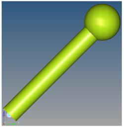
The model will look as shown in Figure 2:
(YZ Rear Plane View)
button.
The model will look as shown in Figure 2:Figure 2. 
- Use the Project Browser to view the model entities and verify their properties.
- In the menu bar, click to check for modeling errors.
-
Run MotionSolve.
-
Click the
 (Run) panel
button.
- For Simulation Type, choose Transient.
- Specify and End time of 2 seconds.
- Click the Simulation Settings button. In the dialog, click the Transient tab and review the integrator parameters.
- Click Close.
- From the Main tab, click the Save and run current model radio button.
-
Click the
 (file browser) and specify the name of the
.xml as pendulum.
- Click Run. Once the run is complete, close the Solver window and the Message Log.
-
Click the
Animate and Plot the Results
Now you will animate and plot the results of the pendulum MDL model run.
-
In the Run panel, click Animate.
A window with the pendulum.h3d results file will load next to the modeling window.
- Click in the new window to make it active.
-
On the Animation toolbar, click the
 (Start/Pause Animation) button to view the
animation.
Note: You can click the button again
 to pause the
animation.
 -
On the Standard Views toolbar, click the
 (Fit Model/Fit All Frames) icon to fit the
visualization in all frames of the animation.
- Click on the MotionView window to make it active.
-
On the Run panel, click Plot.
A plot window with the pendulum.abf results file will load next to the modeling window.
- In the panel, set the Y Type to Marker Displacement, the Y Request to REQ/70000000 Disp Output - (On Ball), and the Y Component as DZ.
-
Click Apply.
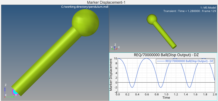
The plot shows the displacement of the pendulum in the Z direction.
-
On the Animation toolbar, click the
 (Start/Pause Animation) button to view the plot and
animation together.
Note: You can click the button again to pause the animation.Your session should look similar to the example shown in Figure 3:
(Start/Pause Animation) button to view the plot and
animation together.
Note: You can click the button again to pause the animation.Your session should look similar to the example shown in Figure 3:Figure 3. 
- In the menu bar, click to close the session.