ERRI
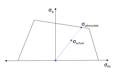
Computing Margin of Safety with ERRI B12 RP60.

= Stress Amplitude
= Mean Stress
HyperLife calculates Margin of Safety using Haigh Diagram or SN curve assigned to the part.
With single or multiple Haigh Diagrams, mean stress correction should be set to INTERPOLATE. If single SN curve, margin of safety is evaluated based on the mean stress model selected. (Similar to Safety Factor evaluated in Stress Life uniaxial: Uniaxial Fatigue Analysis)
From the worst subcase tensors projected in the max principal tensor direction can be applied by toggling.
| Parameter | Description |
|---|---|
| Material | Material assigned to the Part. Material list for selection is created by adding Materials to Assign Material list from Material Db, My Material or HM Material tabs. |
| Material Units | Unit of the assigned material. |
| Plot | Stress Life plot of the assigned material. |
| FL | Fatigue Limit of the assigned material. |
| SE |
Standard Error of Log(N) of the assigned material. Default = 0.0 (Real ≥ 0.0) |
| FKMMSS |
Mean Stress Sensitivity parameters for mean stress correction based on FKM Guidelines. Default: MSS1 = 0.0 MSS2 = 0.15 MSS3 = 0.0 MSS4 = 0.0 |
| Scale | Scale is used to modify the calculated stress during the stress history generation. |
| Offset | Offset is used to modify the calculated stress during the stress history generation. |
| Finish |
Material Surface Finish, a result of manufacturing process. NONE (Default), POLISH GROUND MACHINE HOTROLL FORGE Or USER (any float value between 0.0 and 1.0.) When it is a float value, it will be used to modify the fatigue limit by multiplied with the original fatigue limit. Read more: Other Factors Affecting Fatigue |
| Surf Treatment |
Material Surface Treatment for Material S-N Curve, a process used to enhance the fatigue life. NONE (Default) NITRIDED SHOTPEEN COLDROLL Or USER any float value greater than 0.0. When it is a float value, it will be used to modify the fatigue limit by multiplied with the original fatigue limit. Read more: Other Factors Affecting Fatigue |
| Temperature factor |
Temperature influence can be accounted by applying the temperature factor Ctemp to modify the fatigue endurance limit FL. Read more: Other Factors Affecting Fatigue |
| Kf |
Fatigue strength reduction factor. Default = 1.0 (Real ≥ 1.0) Read more: Other Factors Affecting Fatigue |
ERRI evaluation supports Time Series loading and allows creation of Superposition/Sequential/Range Envelope fatigue events. Refer to: Create Events.