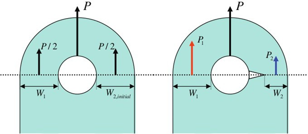
The crack growth solver can redistribute a load during crack growth. Figure 1 shows a typical example of load shedding/redistribution due to a growing crack.
In the case of a single crack in a lug, the cracked section W2 becomes less rigid
than the un-cracked section W1, and part of the applied load is transferred to
section W1. This situation would not happen in the case of two symmetric cracks
because both sections have to hold the same amount of load equal to the half of the
load applied to the lug.Figure 1. Schematic Illustration of the Load Shedding Effect in an Attachment
Lug It has been shown using finite element analysis that this effect is relatively
small, as long as crack stays quarter-elliptical, but becomes significant when the
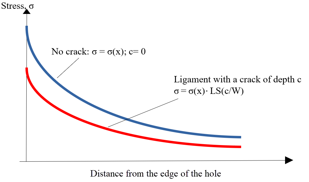
crack breaks through the entire thickness of the lug.Figure 2. The Load Shedding/Redistribution Effect On the Stress Distribution in the
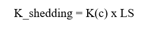
Cracked Ligament Introduction of the load shedding parameter, , enables the estimation of the amount of load taken
by the cracked section ‘W2’ and the estimation of the actual load. Once the shedding
parameter LS is estimated, the shedding parameter could be used to reduce stress at
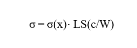
the crack (Figure 2).Figure 3.
Where,
Crack length
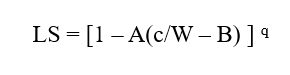
Out of test data, the load shedding parameter was fitted into the following
expression5:Figure 4.
A, B, and q are required inputs. In this particular example, , and were taken.
In actual crack growth calculation, the shedding parameter is used to reduce stress
intensity factor:Figure 5.