
Criteria Settings
Overview of the criteria settings used in QI (quality index) and batch meshing, and in QI-based element checks.
Configure criteria settings using the Criteria Editor. Criteria settings can be saved to a file, and loaded for subsequent editing.
- Access
- Right-click on the Element Quality legend and select Edit Criteria.
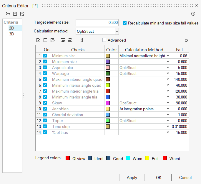
Switch between 2D and 3D criteria from the tree on the left of the dialog.
General criteria settings include:
- Target element size
- Desired element size for the mesh.
- Recalculate min and max size fail values
- Recalculates the minimum and maximum size values in the criteria file based on a newly entered value in the target element size.
- Row Up, Row Down (
 ,
,  )
) - Change the display order of criteria in the Element Quality Criteria
legend.Tip: If you change the order of the element criteria after you have adjusted the threshold values in the Criteria legend, the threshold values will reset to their fail values. It is best to change the order of the element criteria first, and then change the threshold values in the Criteria legend.
- Calculation method
- Select the solver to be used when calculating criteria checks.
- Time step calculator (
 )
) - Minimum length calculator, based on TimeStep, which can be used to calculate the suggested minimum length, based on a material, time step, scale factor, Young's modulus, Poisson's ratio, and density.
Checks can be defined in the table. Each check is displayed in the Checks column, and
the controls and values associated with each check are displayed in the subsequent
columns to the right.
- On
- In the On column, use the checkbox to turn each individual check on/off.
- Color
- Click on the color swatch and select a new color for the element or the
legend.
This can also be done by clicking a color swatch in the Element Quality legend.
- Calculation method
- Select a calculation method to apply for certain checks. Available methods may vary for each check. Click inside each Calculation Method list box to see if alternative methods are available for each Checks entry.
- Fail value
- In the Fail column, edit the fail value for each specific check.
- Ideal, good, warn, worst, and weight value
- The Ideal, Good, Warn, and Worse fields are interpolated or extrapolated automatically.