
Basic Boundary Layer Theory
This section covers concepts such as boundary layer type, flow, separation and transition.
Velocity Boundary Layer
Velocity boundary layer or commonly referred to as boundary layer is a thin layer of fluid formed near a boundary surface where the viscous effects of the fluid are significant.
When a fluid moves past an object or an object moves past a fluid, the fluid molecules right next to the boundary surface stick to it. This causes the molecules just above the surface to slow down because of collision with the molecules sticking to the surface. These molecules consequently slow down the flow just above them. As we move farther away from the surface of the object, the collisions affected by the object’s surface reduces. Thus a layer of fluid is created within which the velocity of the flow gradually changes from zero at the object’s surface to the free stream velocity at a certain distance away from the surface.
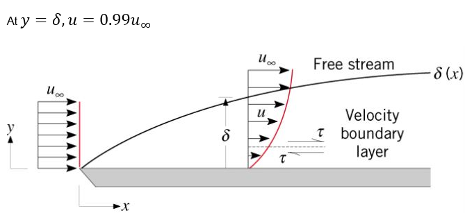
As a result of the loss of velocity, a shear stress is imparted on the object surface defined as
Thermal Boundary Layer
Thermal boundary layer is a region of fluid flow near a solid surface characterized by temperature gradients and heat fluxes. It is a consequence of heat transfer between the fluid and the solid surface and the fluid temperatures are directly influenced by heating or cooling from the surface wall.
The distance at which the difference between the flow temperatures inside the boundary layer and the boundary surface essentially reaches the difference between free stream temperature and the boundary surface temperature is termed as the thermal boundary layer thickness. It is mathematically expressed as:

The local heat flux in a thermal boundary layer is analogous to the shear stress in a velocity boundary layer. The heat flux at the surface is proportional to the temperature gradient. It is defined as
- Laminar boundary layer flow
- Turbulent boundary layer flow
Laminar Boundary Layer Flow
The flow inside a laminar boundary layer is smooth and takes place in layers. Each layer slides past the adjacent layers and any exchange of mass or momentum takes place only between these layers on a microscopic scale. Laminar boundary layer is formed when the Reynolds number is low.
The shear stresses associated with this flow can be calculated using the molecular viscosity .

Turbulent Boundary Layer Flow
As the name suggests turbulent boundary layer flow is more chaotic and is characterized by active mixing of the fluid and momentum across several layers. The exchange of mass, momentum and energy takes place on a macroscopic scale with packets of fluid moving across the layers. A turbulent boundary layer is formed only at high Reynolds number.
In this case the scales of mixing cannot be handled by molecular viscosity alone, therefore turbulent or eddy viscosity has to be modeled in order to proceed with the calculations.

- Outer layer: This layer is sensitive to the properties of the external flow.
- Inner layer: This layer has turbulent mixing as the dominant physics.
- Laminar or viscous sublayer: This layer is attached to the wall where the no slip condition is applied. The shear stress in this layer is dominated by molecular viscosity.

These layers blend into each other and the blending region between the inner layer and laminar sublayer is termed as the Buffer Zone.
As a consequence of intense mixing, a turbulent boundary layer has a much steeper gradient of velocity resulting in a larger shear stress and higher skin friction drag at the wall compared to a laminar boundary layer. In addition heat transfer rates are higher for a turbulent boundary layer. The presence of eddies brings fluid particles at different temperatures into close contact with each other and the heat transfer comes more effective.
Another consequence of mixing is that a turbulent boundary layer has higher momentum near the wall, so it can withstand adverse pressure gradient longer and is less easily driven by the changes in the free stream pressure compared to a laminar boundary layer. This property allows a turbulent boundary layer to be attached to the object surface longer.
Boundary Layer Separation
Boundary layer separation is defined as the detachment of the boundary layer from the surface of the object thus leading to formation of eddies and vortices in the wake. The most important factor which leads to boundary layer separation is an adverse pressure gradient.

A positive pressure gradient, termed as adverse pressure gradient, has the opposite effect on the flow. It further retards the flow leading to a reduction in the velocity near the wall and an increased boundary layer thickness. This continuous retardation causes the shear stress at the wall to drop to zero which then becomes negative causing a reversal in the flow direction near the surface. A region of recirculating flow is developed with formation of large slowly rotating eddies resulting in the flow detaching from the surface of the object. The point at which the velocity gradient and essentially the shear stress reaches zero is termed as the point of separation.
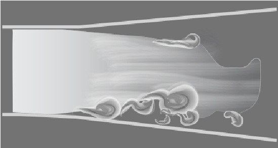
Figure 7 shows the separation of a laminar (top) and turbulent boundary (bottom) layer in a diverging channel.
Depending on the flow conditions, the recirculating flow may reattach to the surface of the body. A number of factors could influence the reattachment. The pressure gradient may turn favourable due to changing flow conditions or the geometry of the body. The other factor is that the boundary layer may transition from laminar to turbulent resulting in a fuller velocity profile that could sustain the adverse pressure gradient and causing the flow to reattach.
Boundary Layer Transition
- Free stream turbulence
- Acoustic Noise (Pressure fluctuations)
- Pressure Gradient
- Surface thermal disturbances
- Surface curvature
- Surface roughness
- Compressibility and high speed flow (transonic, supersonic and hypersonic) transition
These factors along with many other sources of disturbance can cause a smooth laminar flow to break down, enter a transition region and then develop into a turbulent flow. The mechanisms through which a boundary layer transitions can be one of the following:
- Natural transition: This mechanism is prevalent in weak disturbance environments (vibrations, free stream turbulence, adverse pressure gradient, and so on, are absent). The transition occurs gradually and breakdown is reached thorough a linear growth of disturbances. This mechanism is most commonly observed in the flow around a transport aircraft in flight.
- Bypass transition: This mechanism is observed in cases where the initial disturbances in the laminar flow are sufficiently high, caused by factors like surface roughness or high free stream turbulence. The highly non-linear growth of disturbances results in the quick formation of turbulent spots in the flow leading to breakdown, thus bypassing the linear mechanism. This transition mechanism is observed in flows related to turbomachinery where there is high free stream turbulence present.
- Intermediate mechanisms: Aside from the primary mechanisms of turbulence discussed above, there are additional intermediate mechanisms. They include spanwise modulations in the flow, distortions leading to secondary instabilities and direct bypass.
Importance and Practical Applications of Boundary Layer
- Flow over an airfoil: In the aerodynamics industry, the boundary layer is particularly important because it is responsible for a considerable amount of drag on the surface. The airfoils are designed to be thin and streamlined in order to keep the boundary layer laminar, thus reducing the skin friction drag. In situations where there are higher chances of flow separation, it is always preferable that the boundary layer separates towards the leading edge of the airfoil and reattaches somewhere downstream. It is dangerous if the separation occurs near the trailing edge in which case the flow would not reattach, resulting in sudden loss of lift and stalling of the aircraft. There are several approaches used to prevent this problem. These approaches include turbulence generation by tripping the boundary layer using vortex generators, boundary layer suction at the leading edge and reenergizing the boundary layer through blowing.
- Heat exchangers: A large number of production facilities in many industries use processes in which heat transfer takes place within the fluid or between different fluids. In such cases it is always preferable to increase the heat transfer and mixing without paying too high a penalty in terms of increased pressure loss. Some of the approaches used for this purpose include use of internal ribs or fins to increase the internal surface area of the domain, deformation in the flow domain to decrease the hydraulic diameter and disruption of the boundary layer to induce turbulence.
- CFD: The approximations obtained from the thin boundary layer theory greatly reduce the complexity of the equations solved. Mathematically the application of boundary layer theory changes the character of the governing Navier-Stokes equation from elliptic to parabolic. This allows marching in the flow direction, as the solution at any location is independent of the conditions farther downstream.
Aside from the topics discussed above, there are numerous cases where the boundary layer and the physics associated with it have significant applications. A few examples are natural boundary layer in the atmosphere, biometrics of marine organisms, automobile aerodynamics and design of sports merchandise such as golf balls.