New thermal and flow solver
Introduction
Altair® FluxMotor® 2026 introduces a significant enhancement to thermal analysis capabilities by replacing our legacy thermal solver with a new solution based on a generalized lumped parameter model powered by Altair® Flow Simulator. While the frontend interface and workflow remain unchanged, this upgrade brings enhanced accuracy thanks to the integration of a powerful backend solver that couples a lumped thermal network with a fluid flow network.
The previous solver already generated a lumped parameter network adapted to machine geometry. Building on this solid foundation, the new backend model introduces an additional fluid network that enhances our ability to simulate complex convective heat transfer mechanisms - such as cooling circuits and thermal exchanges between the frame and ambient, further improving accuracy.
Enhanced tests
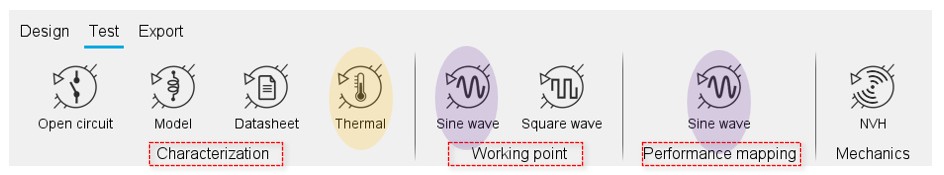
This backend upgrade benefits all the tests, including thermal resolution (both pure thermal and coupled electromagnetic – thermal simulation) for all machine topologies supporting thermal analysis. In other words, our previous solver is no longer used.
- Characterization – Thermal (thermal simulation)
- Steady State
- Transient
- Fitting
- Working point – Sine wave (coupled electromagnetic – thermal simulation
- I-Ψ-N
- Performance mapping – Sine wave
- Efficiency map
 |
|
Test families enhanced by the backend solver update. In yellow thermal tests and in pink coupled electromagnetic-thermal tests |
Reminder – The proposed thermal / flow network
- Customizable thermal network – the constellation method
The proposed thermal network is based on a general scheme where the number of thermal resistances is fixed for some well-known regions in which geometrical changes can be modeled through variable parametrization. These regions are the shaft, the bearings, and the housing (end caps included).
On the contrary, the local grid of some regions is highly dependent on the chosen topology and should be particularized to achieve the essential goals of maximum customization and versatility during the design stage. These regions are mainly the rotor and the stator (including the winding). Due to their high interaction with these areas, the airgap and the end-spaces also require a customized grid.
Stator and rotor geometries, especially the latter, are subject to big changes during predesign, even for a fixed number of slots or poles. Different shapes and number of magnets per pole, the existence of holes in the active parts and shoes next to the airgap are usual. These modifications, which have an important impact on the machine’s performance, are usually difficult to parametrize.
The best solution to this challenge is the use of a customizable grid defined using the constellation method, which can be summarized in the next points:- Since only radial electric machines are considered, the radial cut of the rotor and stator are defined as the rotor part and stator part, respectively. These parts are composed of different surfaces, which are represented by their material (generally steel, air, magnets or conductor) and their central point (i.e., their barycenter).
- Barycenters of neighboring surfaces will be connected by a thermal resistance. These resistances will form the part constellation. Thermal resistances between non-neighboring surfaces are supposed to be infinite.
- Surfaces in contact with external frontiers will be connected to them by thermal resistances (i.e., in the radial plane, these frontiers are the airgap and the shaft for the rotor part and the airgap and the frame for the stator part).
- It is considered that every surface in stator and rotor parts is in contact with both end-spaces; therefore, thermal resistance must link them to these regions. These resistances are the only ones that are not contained in the considered radial plane.
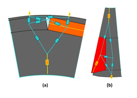
Thermal constellation of a rotor (a) and stator (b) part.
In blue, thermal resistances link internal surfaces. In yellow, resistances link surfaces with part frontiers.
- Coupling with flow network
The fluidic network is coupled with the thermal one at specific points where convection plays a critical role in heat dissipation, most notably between the stator and the cooling circuit and in the interaction between the housing and the ambient air. These areas involve complex and often non-uniform fluid behavior, which significantly impacts the overall thermal performance. By integrating a flow network, the solver can accurately compute fluid temperatures, pressure and speed, leading to more reliable estimations of heat transfer in scenarios where the cooling fluid properties or flow conditions may vary along the considered paths.
- Visualization of the thermal network
The global network can be displayed in a 3D view in Flow Simulator through the dedicated exports.
A dual view is proposed, where the components can be visualized independently or as part of dedicated functional blocks (stator, rotor, shaft, etc.). This visualization allows, at the same time the possibility to show a meaningful global view containing the main heat paths or, on the contrary, to have the deepest insight into one or several regions of interest. Each group can be expanded or collapsed independently.
Once in Flow Simulator, the thermal circuit can be solved, and any kind of modification in thermal resistance values or grid connections can be added.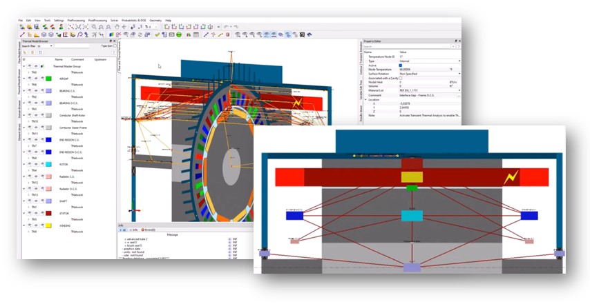
Examples of visualization of thermal networks in Altair® Flow Simulator
Disclaimer: thermal and coupled tests run with previous versions
As a result of this transition, some differences may be observed in the temperature results when comparing simulations run with the previous solver and those using the updated backend. While these differences are expected, a review of thermal results is recommended; if necessary, models could be updated through thermal X factors.
For this purpose, a dedicated process is proposed in a test: Characterization -> Thermal -> Thermal Fitting, now available for all machine topologies supporting thermal analysis: SMPM, RSM, and IMSQ. This test enables easy calibration to align your results with experimental data or legacy expectations when needed.
Looking ahead, this transition not only strengthens the robustness of current thermal simulations but also lays the groundwork for future developments. The inclusion of a lumped flow network will allow the modeling of more sophisticated cooling strategies, which will be progressively integrated into upcoming versions.