Induction machines - Characterization model maps
Positioning and objective
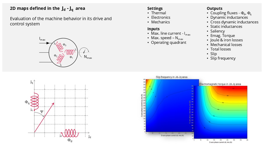
The aim of the “Characterization - Model - Motor - Maps” test is to obtain maps along the two dimensions, Jd-Jq, for characterization of a 3-Phase induction machines.
The identification of the maps is done in order to obtain a rotor field-oriented control (R-FOC), i.e., to model an induction machine with the same vector field reference as for a synchronous machine. In other words, the behavior of the machine is computed with the rotor flux aligned along the d-axis (rotor flux in the q-axis equal to zero). From this point of view, we can say that the FluxMotor test maps for all major machine types are based on the same modeling principles; we speak about a "unified vector model".
Maps computed in Jd-Jq, plane allow to predict the behavior of the electrical rotating machine at a system level.
In this test, engineers will find a system integrator and / or control-command tool adapted to their needs and able to provide accurate maps ready to be used in system simulation software like PSIM or Activate. One of the great advantages of this test is that it allows a vector model of an induction machine to be created, as for a synchronous machine, and then vector control to be applied using the same principles.
 |
| “Characterization - Model - Motor - Maps” - Overview |
The performance of the machine in steady state can be deduced from the results obtained in this test in association with the drive and control mode to be considered.
Main inputs, settings and outputs
- Inputs
Maps are mainly a function of the following user inputs: the maximum value of the line current, the speed and the number of quadrants to be considered.
- Settings
- Temperature of active components: winding and squirrel cage
- Definition of the power electronics parameters
- Definition of mechanical loss model parameters
Note: It is possible to import the current inputs and results from the test “Performance mapping – Sine wave – Motor – Efficiency map”. This will save the computation time related to the identification of the non-linear model; in other words, it will save the computation time related to the finite element solving, which generally represent the main part of the computation time of the test. - Outputs – maps in Jd-Jq plane and curves
- Stator and rotor flux linkage
- Inductances
- Saliency
- Torque
- Stator and rotor losses
- Power electronics losses
- ...
Brief introduction about the main principles of computation
This test is based on rotor field-oriented control condition, i.e. the rotor field is set to be aligned along the d-axis. (rotor flux in the q-axis equal to zero). As previously explained, this results in an identical vector model for IMSQ and synchronous machines (SMPM, SMRSM and SMWF), with the same reference in the Park Jd-Jq plane according to the stator reference phase A. This modelling approach allows a “unified vector modelling” to be obtained for all the FluxMotor test “Maps”.
To be able to align the rotor field with the d-axis, it is necessary to pilot it. To be able to do this for any machine configuration (number of bars) requires a specific modelling method. One of the most efficient and accurate ways is to model the rotor cage with an “n-phase equivalent rotor winding” supplied by an “n-phase sinusoidal current system”.
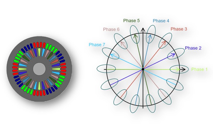 |
| “n-phase equivalent rotor winding” - Principle diagram |
Indeed, an “n-phase equivalent rotor winding” supplied by an “n-phase sinusoidal current system”, allows to obtain a rotor current distribution in slots equivalent to the rotor current distribution in bars of a squirrel cage. In addition, the Park transformation is used to control the current in the Jd-Jq plane and to compute the rotor flux linkage component Φrd -Φrq.
The n-phase equivalent rotor winding is automatically designed and supplied by FluxMotor through an internal process. The ampere-turns are automatically computed according to the classical equation of the stator and rotor magnetomotive force balance between those 2 windings.
The main principle of computation of the model is to supply the stator and the rotor currents over a grid of values (Jd, Jq) and then solve the finite element (FE) model.
After the FE solving, evaluate from the rotor flux computed the “T equivalent scheme” inductances. Inductances allow to compute the Kr coefficient which corresponds to the coefficient that allows to switch from a “T equivalent scheme (any FOC condition)” to an “L equivalent scheme (R-FOC condition)”.
The Kr coefficient is called the “rotor field-oriented control non-linear correction coefficient”. So, Kr is used to correct the rotor current value and then solve a new FE simulation, which must be aligned with the “L equivalent scheme” and ensure the R-FOC condition.
In our experience, due to the non-linearity of the soft magnetic materials, the first use of Kr is generally not accurate enough and an iterative process of computation is used to accurately ensure the R-FOC conditions. The number of iterations required is generally 2, but an advanced input, “Number of iterations for Kr evaluation” allows this to be increased if necessary.
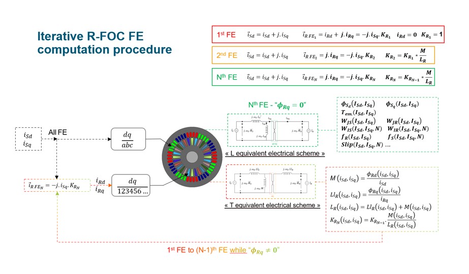 |
| Iterative rotor field-oriented control finite element computation procedure |