Design
Type of shaft
The design of the machine can be considered with or without a shaft. Hence, two
solutions are proposed:
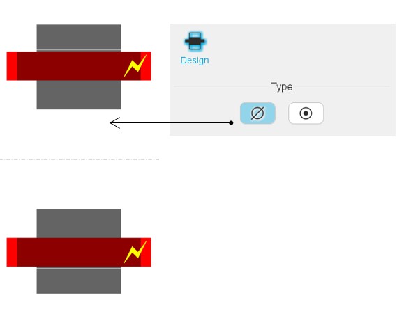
- None: The shaft is not represented and not considered in the rotor design. It is replaced by fluid (like air).
- With shaft: The shaft is represented and considered in the rotor design.
Note: The shaft can be built only with solid material.
 |
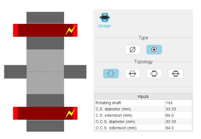 |
| Shaft type: None | Shaft type: Solid |
 |
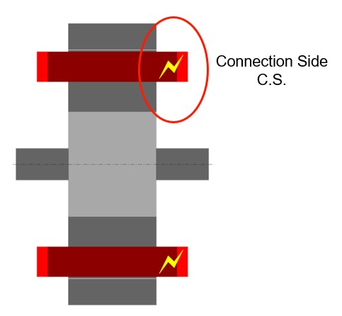 |
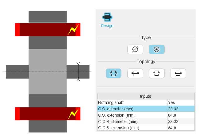
| The dimensions are illustrated with arrows. | The connection side (C.S.) is identified by yellow lightning. |
Type of shaft topology
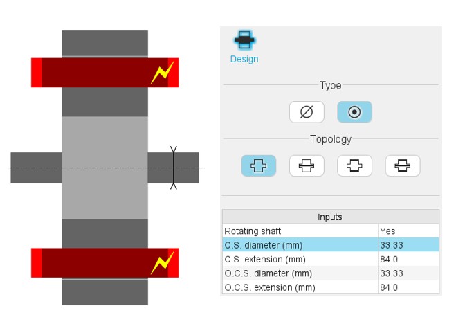
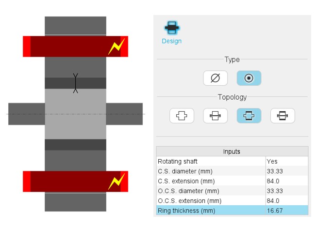
Four types of shaft topology are proposed and illustrated below.
 |
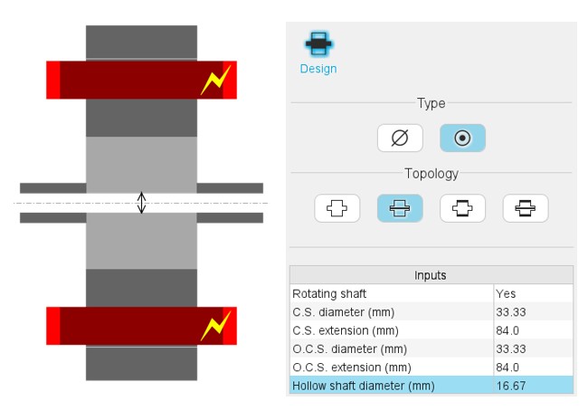 |
| Shaft topology 1: Solid Shaft | Shaft topology 2: Solid with hollow |
 |
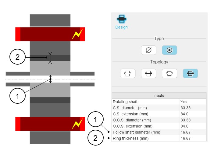 |
| Shaft topology 3: Solid with ring | Shaft topology 4: Solid with hollow and ring |
Inputs – Validity domain
-
Solid shaft inputs:
- Rotating shaft (ROT) - Yes / No
- C.S. diameter (D1) - Connection side end-shaft diameter:]0, 20000] mm
- C.S. extension (L1) - Connection side end-shaft extension:]0, 20000] mm
- O.C.S. diameter (D2) - Opposite connection side end-shaft diameter:]0, 20000] mm
- O.C.S. extension (L2) - Opposite connection side end-shaft extension:]0, 20000] mm
- Solid shaft with hollow inputs:
Idem Solid shaft inputs +
- Hollow shaft diameter (D0) - Inner diameter of hollow shaft:]0, 20000] mm
- Solid shaft with ring inputs:
Idem Solid shaft inputs +
- Ring thickness (THR) - Ring thickness:]0, 20000] mm
- Solid shaft with hollow and ring inputs:
Idem Solid shaft inputs +
- Hollow shaft diameter (D0) - Inner diameter of hollow shaft:]0, 20000] mm
- Ring thickness (THR) - Ring thickness:]0, 20000] mm
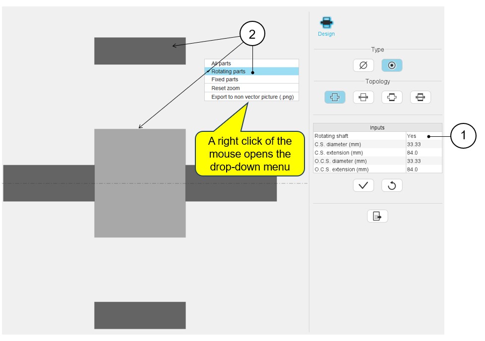
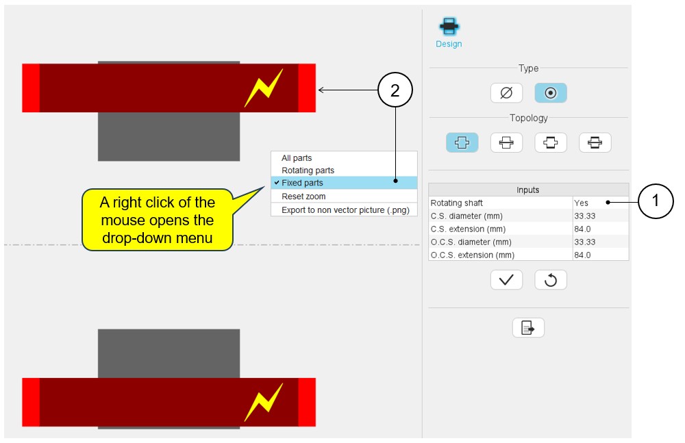
Fix and rotating parts
The rotor can be set as a rotating part or not.
There is a way for displaying the rotating parts or the fixed part.
Note: In the list of user inputs, the “Rotating shaft” (Yes /
No) allows to consider that the rotor rotates or not. Based on this property, it
is possible to display the regions that rotate or that are fixed. A right click
of the mouse opens a dialog box allowing it to display all parts or either
Rotating parts or Fixed parts. The parts are displayed considering the previous
choice. See the illustrations below.
 |
|
|---|---|
| 1 | The shaft is set as a rotating part. |
| 2 | The right click of the mouse opens a dialog box allowing it to display all rotating parts. |
 |
|
|---|---|
| 1 | The shaft is set as a rotating part. |
| 2 | The right click of the mouse opens a dialog box allowing it to display all fixed parts. |
Note: The drop-down menu allows you to display all parts, to
manage the zooming and to export a picture.