Tube conductor mode: geometrical description
Introduction
The tube conductor mode enables a description of unidirectional conductors of variously-shaped cross-section. This cross-section, which must be defined by a series of segments, can be:
- full, possibly rectangular
- hollow, but with a constant layer thickness

General process
The general process of description in tube conductor mode is presented in the table below. (The stages are detailed in the following blocks).
| Stage | Description |
|---|---|
| 1 | Description of a geometric tube (by the user) |
| 2 |
Automatic creation (by the Flux PEEC software) of:
|
| 3 |
Possible modification (by the user) of the physical characteristics of the unidirectional conductor created automatically (material / mesh /…) |
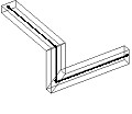
Geometric tube: definition
A geometric tube is a tubular volume defined by a neutral fiber and a cross-section profile.
The neutral fiber, which constitutes the centerline of the tube, consists of segments that make any angles, not necessarily right.
The cross-section is a surface perpendicular to the neutral fiber and is defined by a profile. This profile is a series of segments having not necessarily a right angle between them.
In the case of a full cross-section, the profile represents the outline of this cross-section; in the case of a hollow cross-section it is its centerline.
The volume of the conductor is built by the extrusion of the cross-section profile along the neutral fiber.
Geometric tube: description
The main phases of the description of a geometric tube are presented in the table below.
| Stage | Description |
|---|---|
| 1 | Creation (optional) of geometric parameters |
| 2 |
Creation of tube points*: points for the definition of segments constituent of the neutral fiber |
| 3 |
Creation of the profile, if the cross-section of the conductor is not rectangular:
|
| 4 |
Creation of a geometric tube:
|
| 5 |
Automatic creation (by the Flux PEEC software):
|
* A tube point is compulsorily associated with a geometric tube. It cannot be used for the description of a geometry constructed by assimilation.