Since version 2026, Flux 3D and Flux PEEC are no longer available.
Please use SimLab to create a new 3D project or to import an existing Flux 3D project.
Please use SimLab to create a new PEEC project (not possible to import an existing Flux PEEC project).
/!\ Documentation updates are in progress – some mentions of 3D may still appear.
Example 2: automatic preparation of a series of Flux projects ready to be solved
Objective
The objective is to study 3 specific configurations of a parameterized device.
Example description
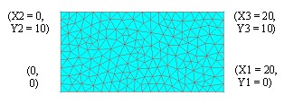
The studied device is a simple geometrical figure (quadrilateral) defined using 6 parameters: X1, Y1, X2, Y2, X3, Y3.
This command file could be used to create different Flux projects in 2D.
Process
The process includes the following stages:
| Stage | Description | Context |
|---|---|---|
| 1 | Preparing a Flux project which contains the base geometry | Flux |
| 2 | Saving in a command file the sequence of the geometry modification with mesh rebuilding | Flux |
| 3 | Modification of the previous command file using the PyFlux language | Text editor |
| 4 | Executing this file to test it | Flux |
Stage 1
To build the basic geometrical figure on which the modifications will be carried out, to carry out the following procedure:
| Step | Action |
|---|---|
| 1 | Open a new Flux project |
| 2 |
Build the geometry:
|
| 3 |
Mesh the device:
|
| 4 | Save the project under the name BASE.FLU |
Stage 1: final result
The project BASE.FLU contains:
- 6 parameters,
- 4 points ((3 are parameterized))
- 4 lines (segments)
- 1 meshed face
Stage 2
To save in a command file the sequence of modification:
| Step | Action |
|---|---|
| 1 | Create a command file ModifParam.py |
| 2 |
Carry out the modification actions:
|
| 3 | Close the command file |
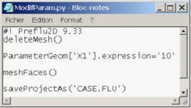
Stage 2: final result
The command file ModifParam.py containing the saved sequence is presented as follows:
Stage 3
To modify the previous command file using the PyFlux syntax:
| Step | Action |
|---|---|
| 1 | Write a function in the PyFlux language, which enables the automatic creation of a Flux project (corresponding to a set of parameters) starting from a base project BASE.FLU. |
| 2 | Write the calls of the previous function to create the 3 desired cases |
| 3 | Save the command file |
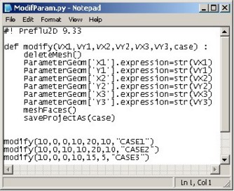
Stage 3: file explanation
The command file ModifyParam.py containing the modify() function and the calls of this function is presented as follows:
| Element | Function |
|---|---|
|
indication on the executable program |
|
definition of the modify() function having as input 7 parameters (6 numerical values to define the geometric parameters X1, Y1, X2, Y2, X3, Y3 and 1 string to define the name of the project) |
|
deletion of the mesh |
|
modification of geometric parameter (X1 takes the value VX1 , converted into string by the method s tr() , …) |
|
meshing faces |
|
saving the project under the name defined by the input parameter case |
|
call of the function to build the first case, … |
Stage 4
Run the command file.
Stage 4: final result
After running the command file, the user has in his/her working directory 4 Flux projects, whose characteristics are given in the table below.
| BASE.FLU | CASE1.FLU | CASE2.FLU | CASE3.FLU |
|---|---|---|---|

|

|
 |

|
| P1: ( 0, 0) | P1: ( 0, 0) | P1: ( 0, 0) | P1: ( 0, 0) |
| P2: (20, 0) | P2: (10, 0) | P2: (10, 0) | P2: (10, 0) |
| P3: ( 0, 10) | P3: ( 0, 10) | P3: (10, 10) | P3: ( 0, 10) |
| P4: (20, 10) | P4: (20, 10) | P4: (20, 10) | P4: (15, 5) |