Creation of Tube Points and Geometric Tubes as well
Principle of the algorithm
If the user chooses the option for the creation of Tube Points and Geometric Tubes as well, the algorithm first creates the Tube Points, as described in the map above, and then he associates them two by two to also generate the Geometric Tubes that approximate the volume of the cable or the wire bonding and that reproduce the electrical current track.
If N is the number of Tube Points created, then the number of Geometric Tubes will be N-1.
The type of the profile and the dimensions of the cross section of the Geometric Tubes are previously chosen by the user, but they can be then modified by a simple editing of the entity.
Data to fill in
Before being able to run the algorithm, the user must fill in the dialog box:
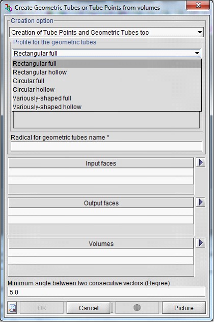
In particular, the user:
- must choose the type of the cross section to assign to the Geometric Tubes and according to this choice he must define the dimensions or the profile
- must define the root for the names to give to the Geometric Tubes which will be created by the algorithm
- must select the input and output faces that define the track of the direction vector
- must select the list of volumes that the algorithm will take into consideration
- can modify the minimal value of the angle between two consecutive orientations of the direction vector, expressed in degrees. This field permits to the user to adjust the accuracy of the approximation.
Obtained result
The image below shows the result obtained on a volume (in turquoise) representing a wire bonding:
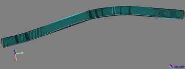
The nine created Geometric Tubes in black lean on ten Tube Points in red. They have a full circular section with a radius of 0.1 mm.
In conclusion, this option of the algorithm permits to the user to rapidly carry out a simulation on a complex geometry, as for each Geometric Tube a unidirectional conductor is automatically created and meshed.