Unidirectional Conductors: meshing of the section
Types of meshing
Several modes to mesh the section of Unidirectional Conductors are provided.
It is possible to distinguish:
-
the manual mode, where the distribution of elements is chosen by the user
-
the automatic mode, where the distribution of elements is fixed by the software according to the frequency
These different modes are presented in the table below and detailed in next blocks.
| Manual discretization … | Definition | |
|---|---|---|
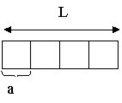
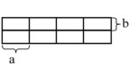
| uniform |
uniform distribution (elements of the same size) |
|
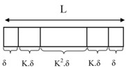
| geometric * | geometric distribution (smaller elements at the periphery) |
|
| “Automatic” discretization … | Definition |
|---|---|
|
according to the reference frequency |
adapted meshing according to the reference frequency of project it reduces the number of meshes without decreasing the quality requirements of the simulation |
|
according to a given value of frequency* |
adapted meshing according to a given value of frequency , associated to the conductor it would be the automatic meshing of the conductor if the reference frequency was equal to this given value of frequency |
Uniform meshing
The technique is not implemented in the same way if the conductor is resulting from a Geometric Tube or a classic geometry description (by Assimilation). Moreover, the conductor section for Geometric Tubes can be rectangular, variously-shaped full or variously-shaped empty, as described in the table below. Consequently, the parameter setting required from the user varies from one case to the other.
| Conductor | Description |
|---|---|
| Geometric Tube with a rectangular section |
|
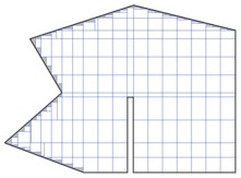
| Geometric Tube with a variously-shaped full section and classic geometry description (by Assimilation) |
Consequently, the global mesh of the section can become non-conform. |
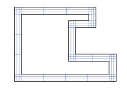
| Geometric Tube with a variously-shaped hollow section |
|
Geometric meshing
This meshing technique is available only for rectangular conductors resulting from a Geometric Tube and is efficient mainly at high frequencies.
When choosing a geometrical mesh for a section of a Tube Conductor, the user has to fill out:
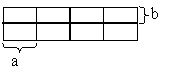
- numbers n and m of the PEEC elements according to which the two sides of the profile (width and height) are subdivided;
- concentrations K (along the width) and H (along the height) of the elements. The values, which must be positive, represent the relationship between the sizes of two successive elements.
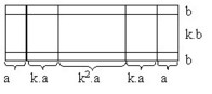
The Flux PEEC software automatically determines the size of all the elements: the basic element ( a along the width L and b along the height T) is calculated by means of the following formulas:
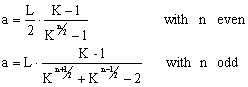
The calculation of b relies on the same formulas where L, K , n are replaced by T, H and m , respectively.
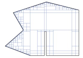
An example of geometric mesh is shown in the figure below:
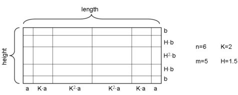
It is worth noting that for a concentration value equal to 1, the user has indeed chosen a uniform mesh in the direction considered.
It would be reasonable from the user to make sure that the size of the a and b elements be comparable to the skin depth thickness, in order to correctly model the phenomenon of electromagnetic field diffusion. To do that, he must:
- choose the number n of the elements he wishes, for example 3, 4, 5, or 6 ;
- calculate the optimal value of K by means of the following formulas:
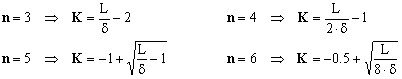
where δ is the skin depth thickness that can be estimated by the expression reported in § Choice and definition of the application .
Automatic meshing according to the frequency
This technique is considered the most efficient, because it combines the very good quality of obtained results and the minimization of the number of meshes.
For conductors resulting from a Geometric Tube the frequency considered by the Flux PEEC software can be the frequency of reference of the project or another one chosen by the user ; the algorithm of the mesh is identical.
The technique is not applied in the same manner if the section is rectangular, variously-shaped full or variously-shaped hollow.
However, for conductors resulting from a classic geometry description (by assimilation) only automatic meshing according to the reference frequency is available.
Different cases are summarized in the table below.
| Conductor | Description | ||||||||||
|---|---|---|---|---|---|---|---|---|---|---|---|
| Geometric Tube with a rectangular section |
The number of elements in the two directions of the section is imposed by the software; it depends on the skin depth thickness (and implicitly on the frequency) and it is always inferior or equal to five. The details are presented in the table below:
|
||||||||||
| Geometric Tube with a variously-shaped full section and classic geometry description (by Assimilation) |
Depending on the thickness of skin depth (and implicitly on the frequency), the software proceeds to the positioning of the mesh elements in the following way:
|
||||||||||
| Geometric Tube with a variously-shaped hollow section |
The algorithm is very similar to the algorithm used for the uniform mesh of variously-shaped hollow sections, except that: the maximum width of the PEEC elements into which to subdivide the profile perimeter is not chosen by the user, but is automatically evaluated by the software and corresponds to the skin depth thickness calculated at the reference frequency. |
||||||||||