Model Construction Steps
Planning
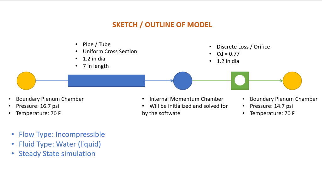
The first step of any successful endeavor is to create a solid plan. Modelling a flow and/or thermal network is no exception. While there are many tools which can help in planning, a classic and practical way would be to start with a simple drawing or sketch. Example sketch below.
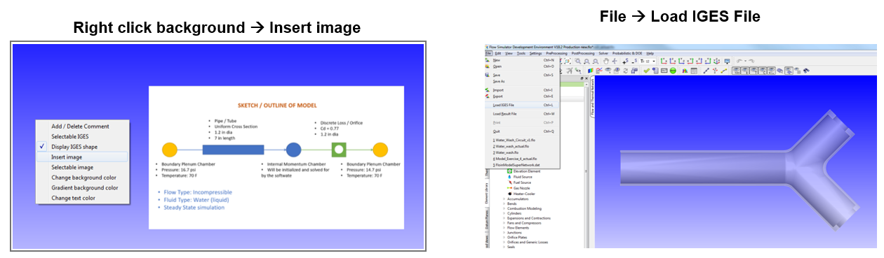
Loading Image/Geometry
Flow Simulator allows the user to import geometry information in the iges form, as well as any image file. This will help visualize the engineering problem in greater detail.
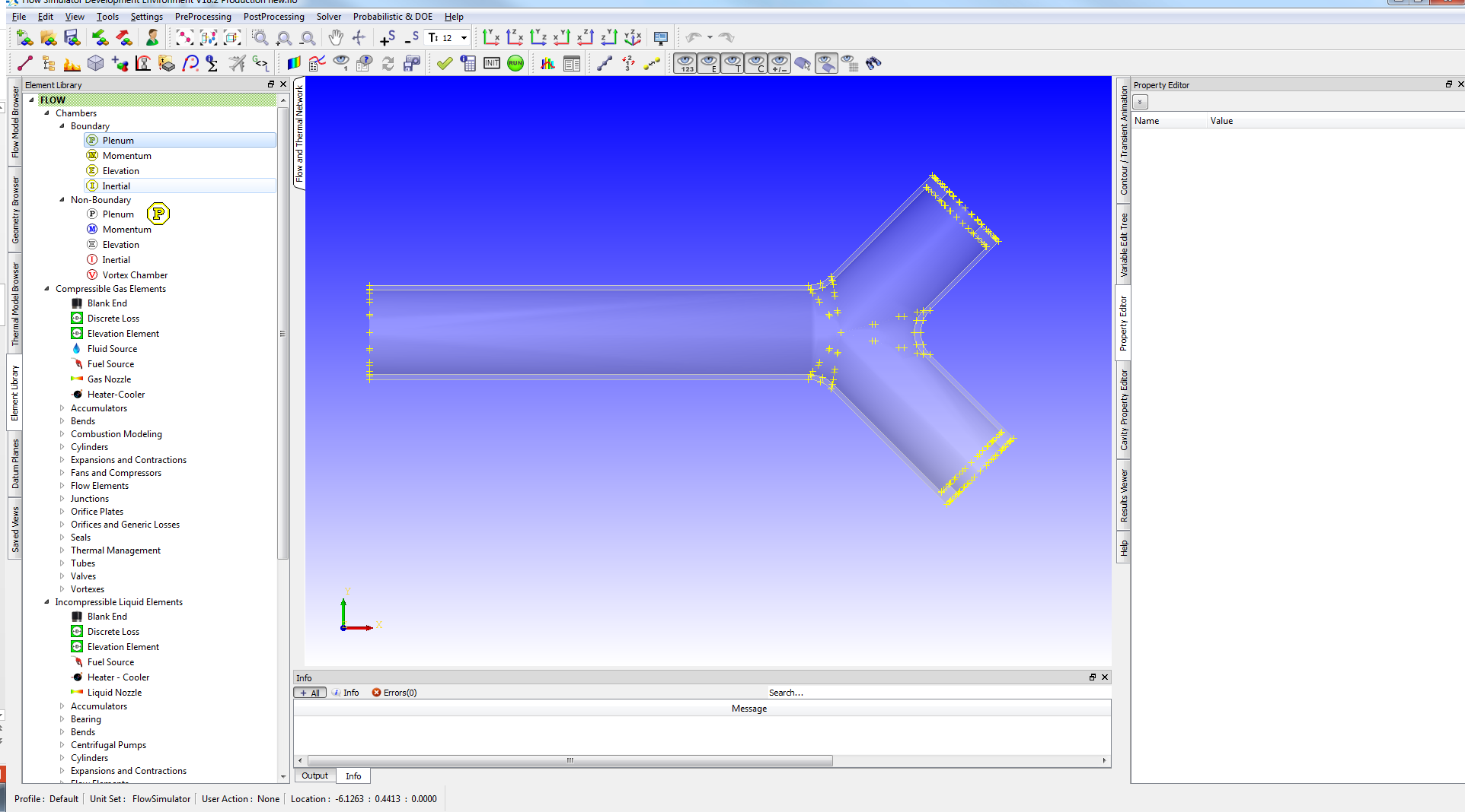
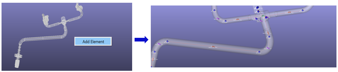
Another important feature for better 3D model building experience in Flow Simulator GUI is mapping of elements & chambers to iges Vertices. Flow simulator allows you to access all the vertices of IGES, user can press SHIFT button while placing the elements/chambers in GUI to highlight the iges vertices as shown below.
Flow Simulator enables to import CAD geometry and automatically generate Flow Simulator elements based on the selected faces. Face Recognition functionality enables users to select faces from their CAD geometry and creates elements automatically and inserts at the selected faces. Moreover, all the geometrical values of diameter, length, angle will be measured and filled in Property Editor automatically. The available elements are Tube, Bend, Junction, and Canonical Transaction.
Defining Boundary Conditions & Choosing Elements
- Define and locate boundaries of the model
- Model extent depends on the goal for the model and the location of known information.
- Place boundaries where the pressure and temperature (or flowrate and temperature) are known.
- Example: In a gas turbine engine system model the gas path Pressure and Temperature are usually known and good places for boundaries.
- Define and locate flow restrictions (or pumps, fans, etc..)
- Type of element depends on geometry of the restriction (orifice, tube, valve, seal …)
- Locations of restrictions also determines where internal chambers will go.
- Rotor stator models also require planning of cavities and vortexes.
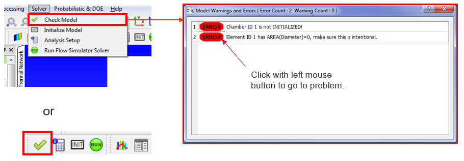
Checking Model
Before running the model, Flow Simulator allows the user to check for typical errors via a single button
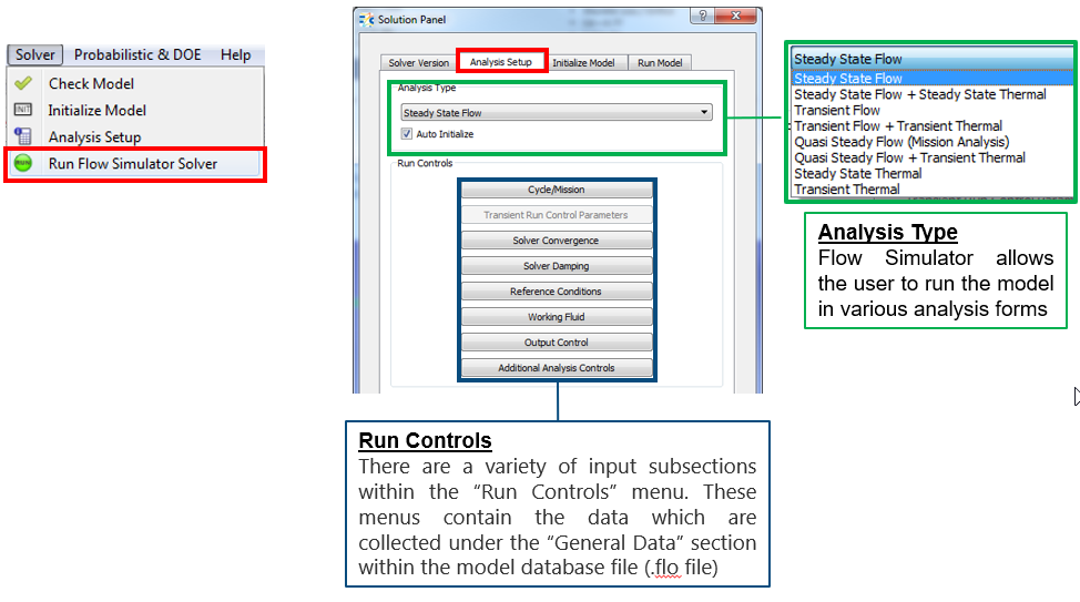
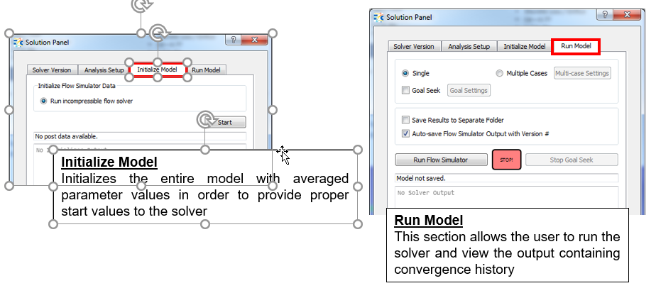
Running Model
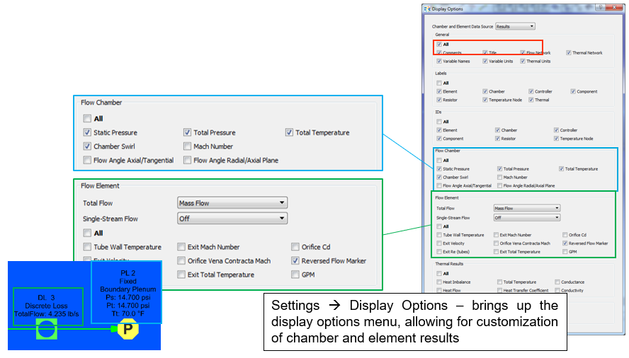
Review Results
Results from the (*.res) file automatically load into the GUI and show chamber and element results.
- Chamber results contain pressure and temperature values
- Element results contain flow rates