Building Blocks for Fluid Systems
Chambers
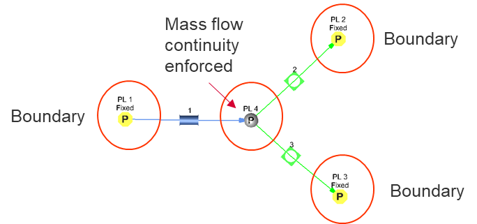
- Chambers connect elements.
- Each element has an upstream and downstream chamber.
- Hold Pressure, Temperature, Velocity
- Boundary Chambers have known P, T, V
- Non-Boundary (Internal) have solved P, T, V
- Solver convergence based on mass flow continuity at the internal chambers.
- Chamber Types : Plenum, Momentum, Inertial, Vortex, Elevation, Wind Bc
| Frame |
Swirl Values (VEL_Air / VEL_metal) |
Comments | |
|
Plenum
|
Relative | 0 or 1, (stationary or “onboard” rotating part) |
|
  Momentum Momentum |
Relative | 0 or 1, (stationary or “onboard” rotating part) |
|
  Elevation Elevation |
Absolute | 0 (always use on stationary) |
|
  Inertial Inertial |
Absolute | Any |
|
| Vortex |
Absolute | Any |
|

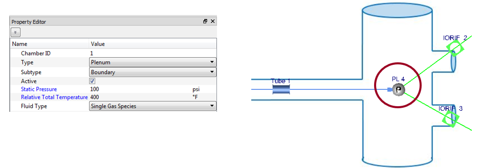
Plenum Chamber
- Variables: Static Pressure, Total Temperature (Absolute or Relative), Fluid Type
- Uses:
- Where velocity = 0 such as a large tank or cavity.
- Usually stationary parts
Momentum Chamber
- Variables: Static Pressure and Total Pressure (Absolute or Relative), or Mach Number, Total Temperature (Absolute or Relative), Fluid Type
- Can enter 2 out of these 3 items: Static Pressure, Total Pressure, Mach number. 3rd item is calculated
- Uses:
- Where velocity (fluid momentum) is passed from upstream to downstream elements
- Usually stationary or inside of rotating parts
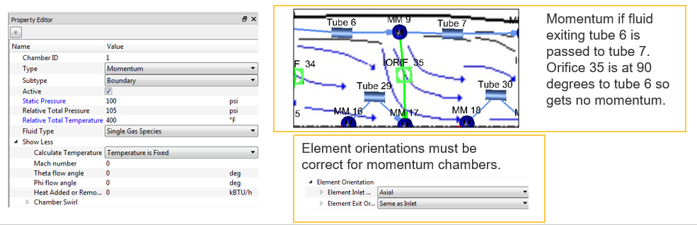
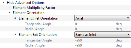
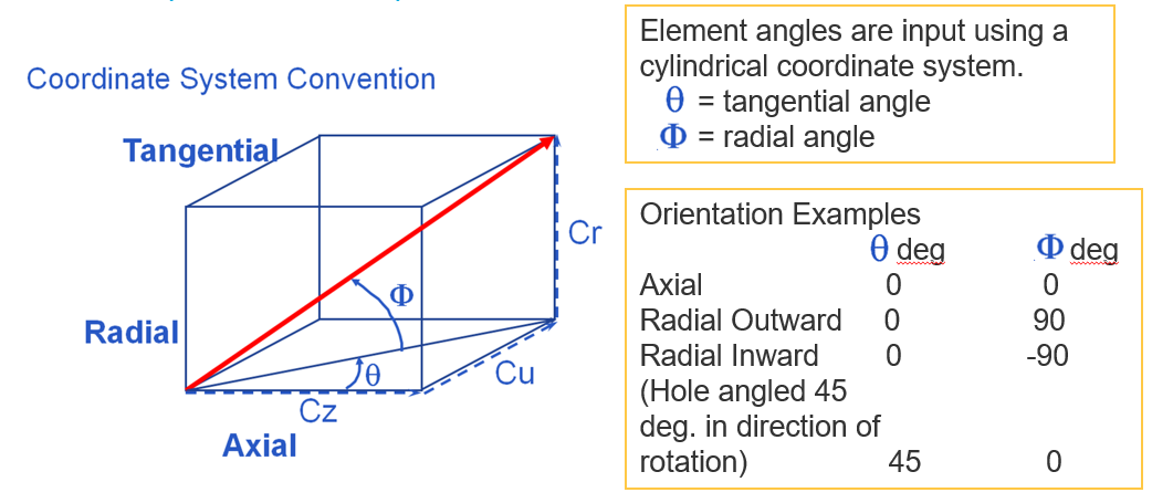
Angles:
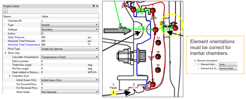
- Element orientation is critical to correct modeling when using momentum and inertial chambers.
- The relative angle difference between elements determines how much dynamic head is passed through the chamber to the downstream element.
Affects the source pressure that forces air through the downstream element. If elements are aligned the source pressure = total pressure. If elements are not aligned the source pressure < total pressure. If elements are 90 deg. different angles source pressure = static pressure.
- Input found under Advanced Options in most element panels.
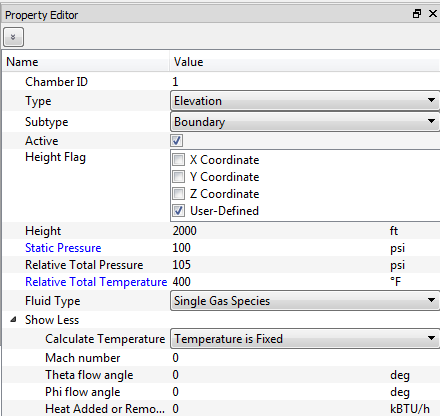
Elevation Chamber
- Variables: Height, Static and Total Pressure or Mach Number, Total Temperature, Fluid Type
- Uses:
- Where there are significant changes in elevation that affect the pressure
- Stationary Parts
- Usually Incompressible Liquid
Inertial Chamber
- Variables: Static and Total Pressure or Mach Number, Total Temperature, Swirl, Fluid Type
- Can enter 2 out of these 3 items: Static Pressure, Total Pressure, Mach number. 3rd item is calculated
- Uses:
- Usually cavities in rotating models.
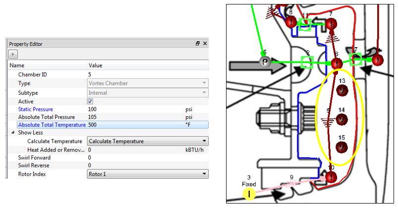
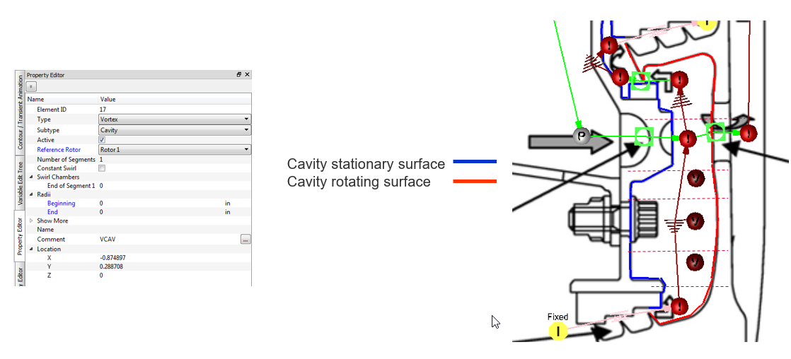
Vortex Chamber
- Variables: Static and Total Pressure or Mach Number, Total Temperature, Swirl, Fluid Type
- Can enter 2 out of these 3 items: Static Pressure, Total Pressure, Mach number. 3rd item is calculated
- Only chamber that is not attached to the end of elements.
- Cannot be a boundary
- Uses:
- Vortex elements and cavities in rotating models.
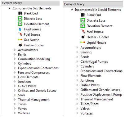
Elements & Components Overview
- Represents a flow path between one chamber and another
- Many different element types and subtypes are used to represent a flow circuit using the correct flow characteristics for a given feature – ranging from simple restrictions like tubes and orifices, to complex restrictions such as valves and seals.
- Grouped into both compressible (gas) elements and incompressible (liquid) elements.
- Flow rates and derivatives are calculated iteratively by passing through each element type-specific subroutine until mass continuity is achieved across all internal chambers.
- Most elements are restrictions. Flow rate is calculated based on the pressure drop from the upstream chamber to the downstream chamber.
- Some elements are pressure rise elements such as pumps and fans.
Restriction Elements
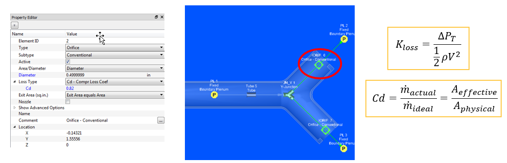
Orifices and generic losses
- Variables: Cross-Sectional Geometry and Losses
- Losses: Cd, Kloss. Constant or variable.
- Should be used for restrictions that do not have large L/D
- Uses:
- General-use element type
The CDCOMP subtype will calculate the loss but the other types require the user to enter a Cd or K.
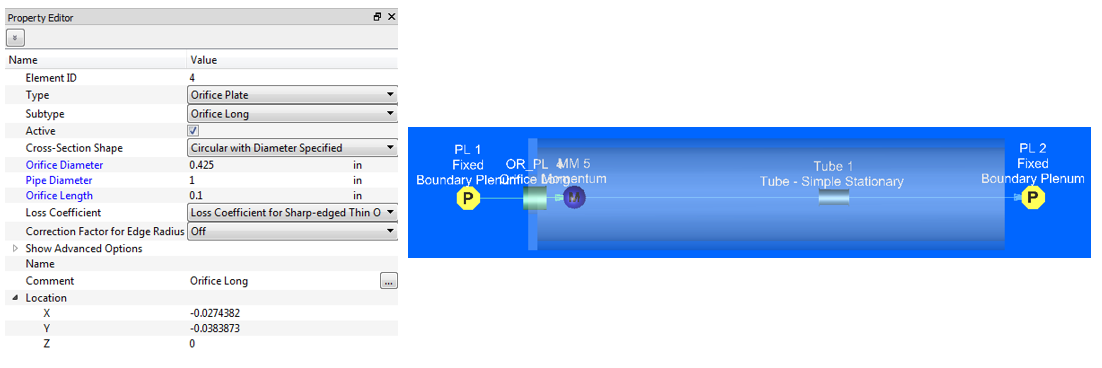
Orifice Plates
- Variables: Orifice Cross-Sectional Geometry, Pipe Diameter
- Uses:
- Calculating loss for an orifice plate in a pipe/tube.
- Loss correlations based on circular holes in a circular pipe.
Tubes / pipes
- Variables: Diameter, Length, Number of Stations, Surface Roughness
- Include laminar and turbulent friction
 , rotation, and heat transfer effects
 - Uses:
- Restrictions with large L/D where frictional effects would play a large role
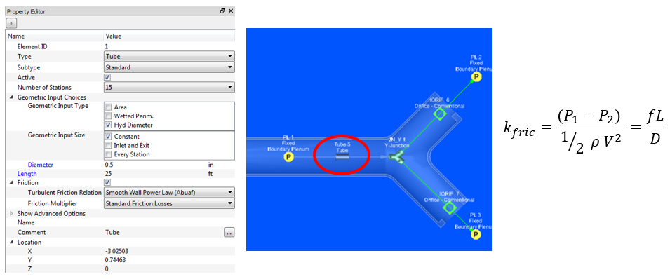
- The tube elements solve the following equation at each segment of the tube.
- Subsonic Compressible

- Incompressible
- The tube element converges each outer iteration when the velocity (mass flow) used in the equations above allow the pressures at the first and last tube station to match the pressures in the upstream and downstream chambers.
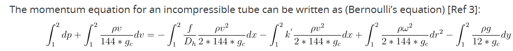
Bends
- Variables: Bend Angle, Bend Radius, Cross-Sectional Geometry, Roughness
- Can model a variety of different bend geometries (see subtypes)
- Uses:
- Connect 2 tubes/pipes
- A more robust modeling of bends, including more loss data available that those included with the tube element type.
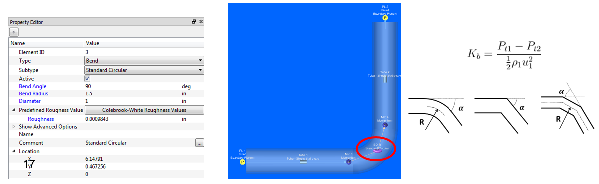
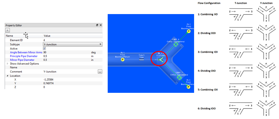
Junctions
- Variables: Arm Angle, Principle Diameter, Minor Diameter
- T- Junction has straight through pipe with a side branch
- Y-Junction has a principle pipe with two minor branches
- Uses:
- Connect 3 tubes/pipes
- Models flow splits or unions, specifically to include a loss model
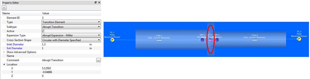
Expansions / Contractions
- Variables: Inlet / Exit Cross-Sectional Geometry
- Can use a variety of different expansion or contraction models
- Uses:
- Models either gradual (conical) or stepped (abrupt) changes in cross-sectional geometry
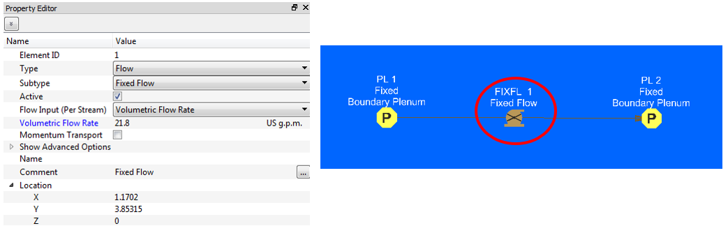
Flow Elements
- Variables: Flowrate, Reference Flow, Reference Pressure Parameter
- Uses:
- Specify pre-defined flowrate either outright, or based on pressure parameter, or reference flows (combo flow)
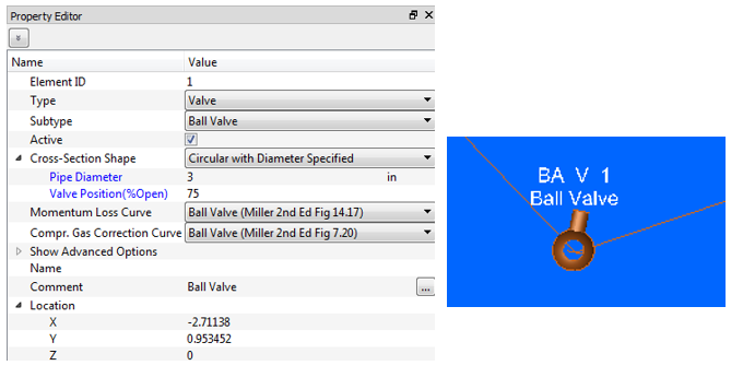
Valves
- Variables: Momentum Loss Curve, Cross-Sectional Geometry, Valve Position
- Uses built in empirical loss data or user supplied loss data.
- Uses:
- Either for control or check valves
-
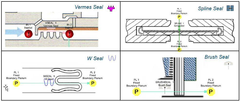
Seals
- Compressible Flow
- Uses:
- Calculates loss from a range of different types of seal configurations common in gas turbines.
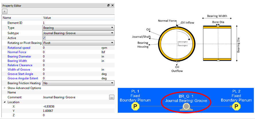
Bearings
- Variables: Rotation Speed, Normal Force, Bearing Diameter & Width, Relative Clearance
- Can choose whether to include heating from friction
- Uses:
- To simulate steadily loaded journal bearing, determining flow rate (and optionally, heating)
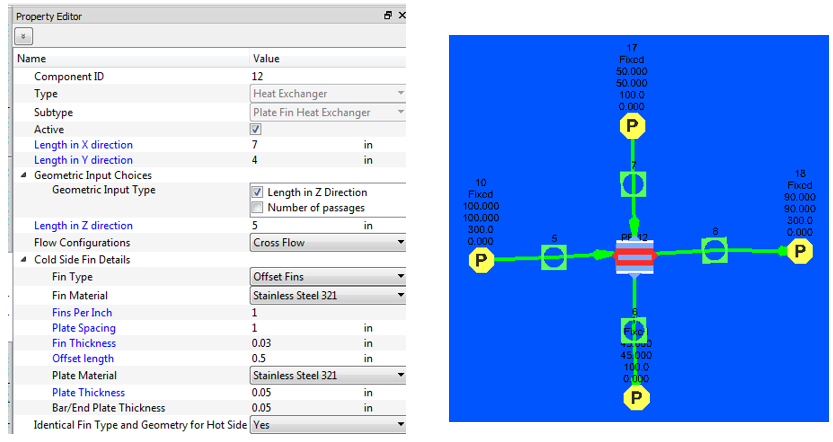
Heat exchanger
- Uses a lumped e-NTU method to calculate heat transfer between to fluid streams.
- Behaves like a chamber with 4 element attachment points.
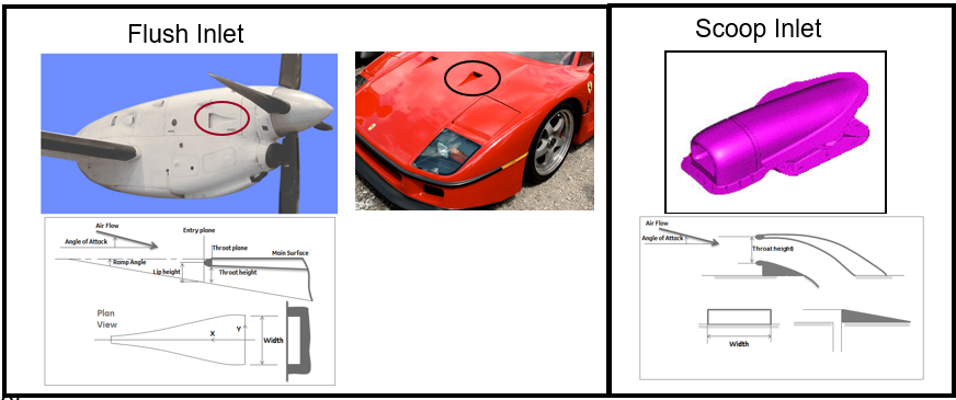
NACA Scoop
- Variables: Geometry
- Bring external airflow of high velocity into a cavity with minimal pressure loss.
- Uses: Nacelles
Pressure Rise Elements
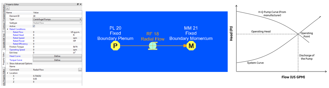
Centrifugal Pump
- Incompressible liquids only
- Requires a Pump Characteristic curve.
- The point where the derived pressure loss flow rate curve intersects the pump curve defines the operating point of the system.
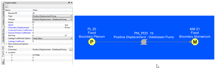
Positive displacement Pump
- Incompressible liquids only.
- Positive displacement pump behaves like a Fixed Flow element where the flow gets calculated from volumetric displacement provided by manufacturer for the specific pump
Fans and Compressors
- Compressible gas only.
- The user needs to provide performance data for a machine that is dimensionally
similar to the one they wish to simulate, but which may differ in:
- Operating conditions (Temperature & Pressure)
- Gas Properties (i.e. Inlet Density)
- Rotational Speed
- Impeller Diameter
Transient Flow Analysis Items
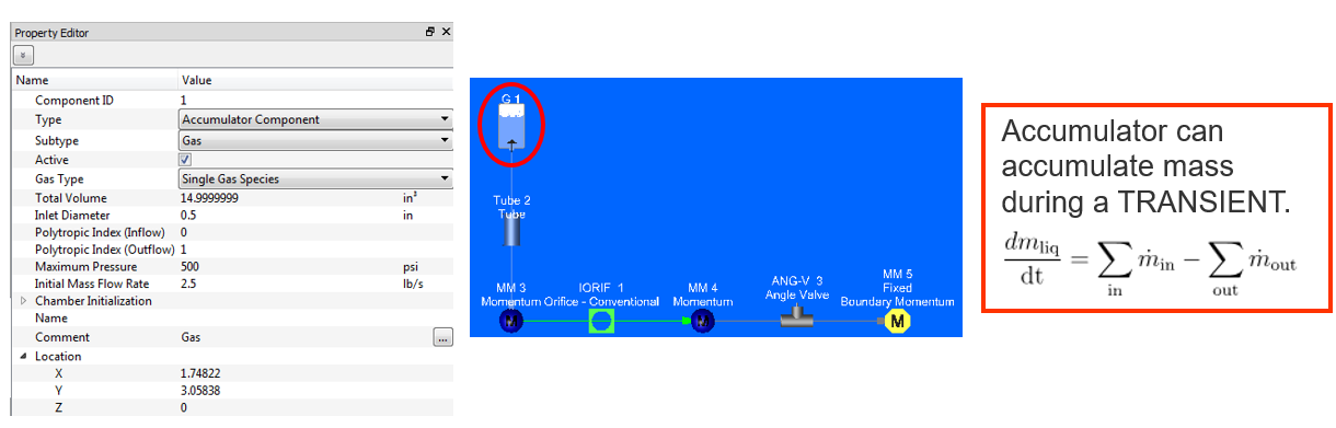
Accumulators & Tanks
- Variables: Volume, Inlet/Outlet Geometry, Inlet/Outlet Loss, Fluid Type
- Actually a ‘Component’, behaves like chamber in terms of connectivity (used up or downstream of an element)
- Uses:
- Control volumes (such as tanks) that are either filling / emptying (or both)
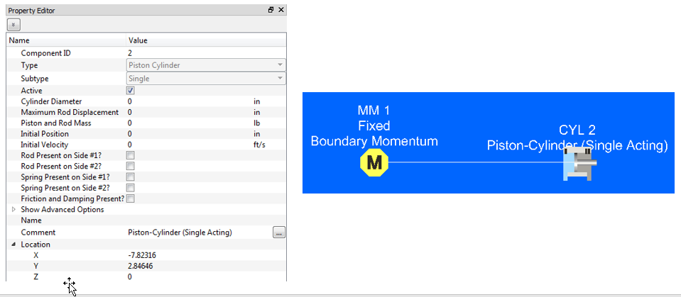
Cylinders
- Variables: Diameter, Max Rod Displacement, Piston and Rod Mass, Initial Position and Velocity
- Can optionally include friction and damping effects
- Uses:
- Modeling of either a one-sided or two-sided piston in cylinder
Rotating Model Building blocks
Vortex elements
- Used to model rotating flow fields that do not have a significant flow restriction.
- Calculates pressure and temperature changes due to rotating flow.
- Uses:
- Rotating machinery such as gas turbines
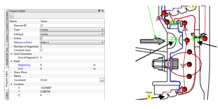
Cavities
- Not an element or chamber
- Used to model rotating flow fields
- Uses angular momentum balance to calculate fluid swirl.
- Fluid swirl is used in vortex elements.
- Uses:
- Rotating machinery such as gas turbines
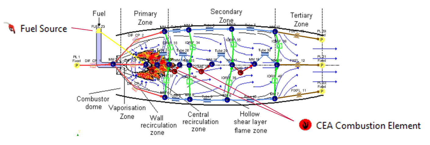
Combustion modelling
- Heat increase due to combustion using NASA CEA
- Fuel (reactants) and Air (oxidizer) tracked through network
- Fuel Source adds fuel to the network
- CEA Combustion Element
- Uses CEA to increase gas T
- Decrease Pressure due to heat addition
- Use series of elements for incomplete (rich) combustion upstream
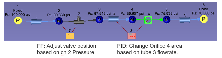
Controllers
- Controllers are used to change chamber and element inputs while the solver is
running.
- Example: Change a valve position based on chamber pressure
- Controllers use “Gauge” variables to “Manipulate” the chamber or element
inputs.
- Example: Gauge variable = chamber pressure and Manipulate variable = valve position
- 3 types of controllers
- PID Controller: Use PID logic to determine element variable value based on solution from another entity
- Mission BC Controller: Defines time-dependent variations of a variable
- Feed Forward Controller: Change element variable based on solution from another entity
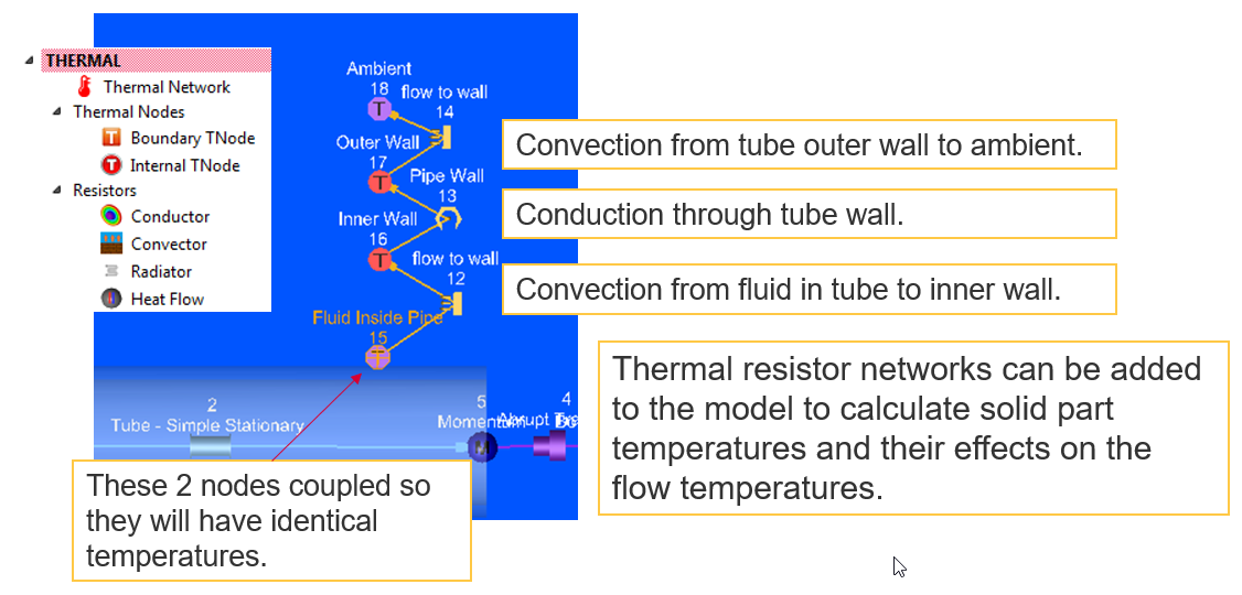
Thermal Network Items
Thermal network entities are typically used to model;
- heat flow through solids, liquids or gases,
- heat flow from a surface to another surface via electromagnetic waves
- heat flow applied directly at a point
Flow Simulator enables to integrate thermal resistances of conduction, convection and radiation, and direct heat application either as a standalone network or as a thermal network coupled with flow network to generate combined results. Moreover, Steady-State and Transient analyses are available for both options.