
Gravity Process
Define the parameters for a gravity sand casting or gravity die casting process.
Location: Gravity is an option on the Basic Setup icon on the Casting ribbon.

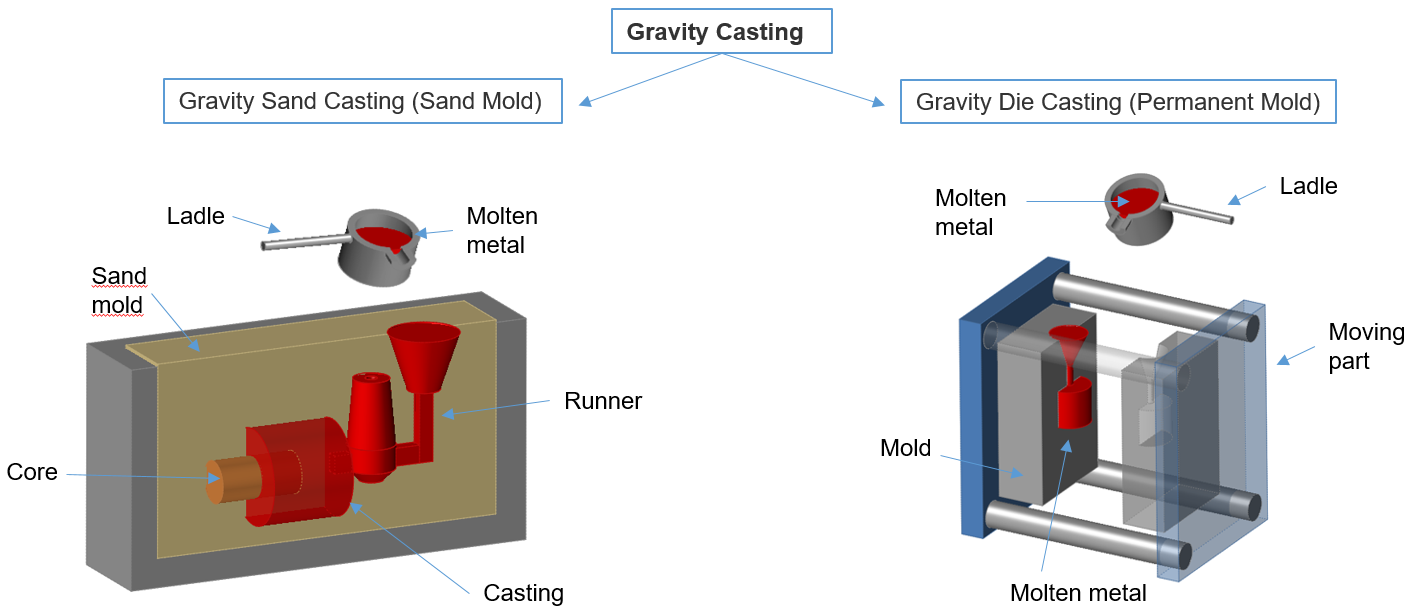
Gravity sand casting has few limits on size, shape, and weight, with low pattern and material costs. However, it is generally less accurate than die casting and has a low production rate due to the destruction of the molds. Gravity sand casting generally uses ferrous metals such as stainless steel, carbon steel, and cast iron.
Gravity die casting is a type of permanent mold casting generally used for the production of small, simple metal parts such as gears, pistons, and wheels. It is similar to gravity sand casting but with a permanent mold, making it a better choice for high production volumes. Gravity die casting generally uses non-ferrous metals such as aluminum, magnesium, and copper alloys, although iron and steel parts can also be cast using graphite die molds.
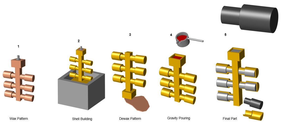
- The wax pattern is created manually or by injecting wax in a mold.
- The ceramic mold (investment) is created by coating the wax pattern by dipping it into sand.
- The shell mold is dewaxed by heating the pattern.
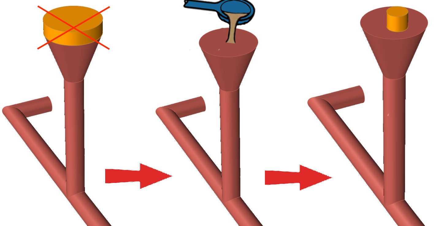
- The molten metal is pored into the hollow mold.
- The shell mold is knocked out to get the final cast part.
Define Gravity Parameters
-
Click
 next to the
Basic Setup icon, then select Gravity.
next to the
Basic Setup icon, then select Gravity.
-
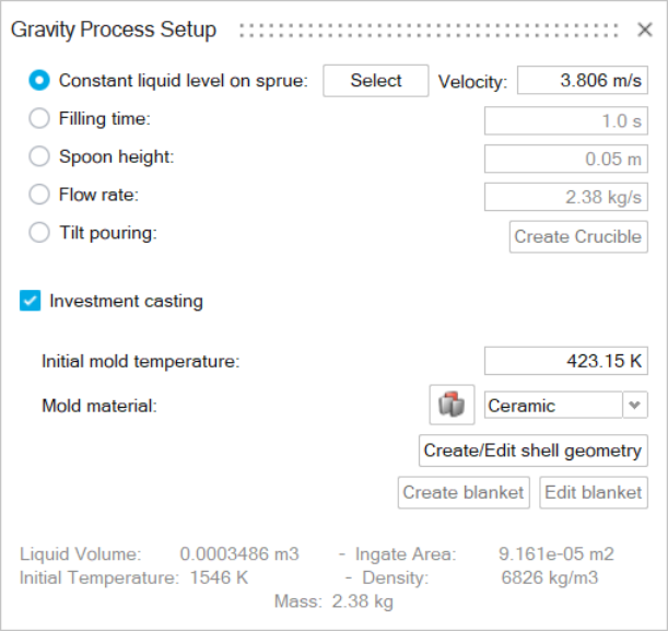
Select Constant Liquid Level on Sprue,
Filling Time, Spoon Height,
Flow Rate, or Tilt
Pouring.
 Note: If you select Constant Liquid Level on Sprue:
- When you click Select, you can then select the point on the sprue where the liquid level should remain constant.
- If more than one ingate is present, you can select a liquid level for each ingate.
- You can also change the initial pouring velocity of the material if necessary.
Note: If you select Tilt Pouring, the Create Crucible button becomes active and a new dialog opens to enter details about the rotation.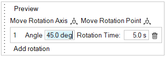
-
Optionally, you may select Investment Casting.
Click the Create/Edit shell geometry button. The shell mold will be simulated allowing for analysis of mold temperatures over time. You will see a visual rendition of the shell mold. Use the microdialog to define shell thickness. Enter the desired temperature in the Initial Mold Temperature field in the Gravity Process Setup window. Use the menu to select the type of material for the shell mold. Click the Materials Database icon
 to select a specific material for the shell mold.
If desired, click the Create blanket button to create an additional insulating layer around certain portions of the mold. Select a surface on the model to designate the blanket's position. Control-click to select additional surfaces. Use the microdialog to define the blanket's thickness. When you're satisfied, click the play button in the microdialog to create the virtual blanket.
- Define the parameters.
Gravity Options
- Constant Liquid Level on Sprue
- Select this option to maintain a constant liquid level on the sprue during filling. Click Select, then click the point on the sprue where the liquid level should remain constant. The flow rate will change during the filling by adjusting the inlet area to keep the selected level constant.
- Velocity
- Use this field to specify the initial velocity of the poured material, or use the default. When the liquid level reaches the specified point, the velocity will adjust to keep the level constant.
- Filling Time (s)
- Select this option if you have calculated the exact filling time
required for your process. Inspire Cast
internally converts the filling time to velocity.

- Spoon Height (mm)
- Select this option when you have totally manual ladle operators. Spoon
height is the distance between the ladle and the mold when the liquid is
being poured. If you don’t know this value, use a value around 10–30 mm.
Inspire Cast internally calculates the
velocity based on the spoon height.

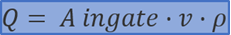
- Flow Rate (Kg/s)
- The flow rate is the poured metal volume in Kg divided by the filling
time in seconds. This parameter can be calculated when using an
auto-pour ladle, bottom-pour ladle, stop-and-rod ladle, etc.
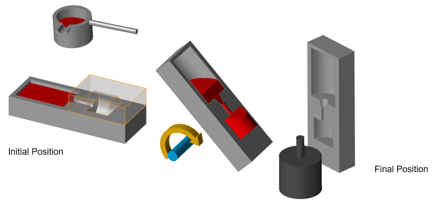
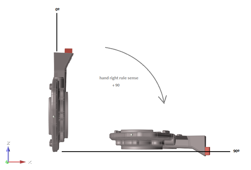
- Tilt Pouring
- Rotation axis
- Select X, Y, or Z to define the axis of rotation. The tilting rotation follows the same order as the XYZ coordinate axis; if you select Y as the axis of rotation, then Z will rotate over X; if you select Z, then X will rotate over Y, and so on.
- Move
- Move the center of rotation. Right-click to return to the Tilt Pouring parameters.
- Rotation table
- Enter values in the time vs angle table. To set a positive or
negative angle, check the sense of rotation from the final
position to the original position following the right-hand rule
to determine the sign.
- Preview
- Click Preview to check that the sense of rotation selected is the correct one.
- Investment Casting
- Shell thickness
- As the mold in investment casting is only a thin shell, Inspire Cast will use a virtual mesh for it instead. Enter the shell thickness of the investment mold to simulate its effect on the part.
- Initial mold temperature
- Enter the shell temperature at the moment of filling the mold.
- Mold material
- Use the dropdown menu to choose the type of shell mold material, and use the materials database to select a specific material.