Run Analysis
Define and run a filling analysis, solidification analysis, or both.
You need to define a cast part and add gates and other optional components before running an analysis.
-
Click Run Analysis on the Analyze icon.

-
Define the parameters.

Option Description Name Type the name of the run. (By default, the name of the model is used.) Average Thickness Select this to enter the average thickness of the part. Element Size is updated with changes to this value. Element Size Select this to enter the element size of the mesh, which dictates the quality of your results. In general, the smaller the element size, the more accurate the result, but the slower the analysis will run. Speed/Accuracy If you select Average Thickness, you can use this slider to adjust the speed and accuracy of the analysis. Faster increases the element size, while slower increases the accuracy. Element Size reflects this change. Run a filling analysis When running a solidification analysis only, the starting temperature will be the same throughout the entire part. When running both filling and solidification analyses, the temperature distribution at the end of the filling analysis will be used as the starting point for the solidification analysis.
Run a solidification analysis Compute deformation Include deformation in the analysis. Fast/Robust If you select Compute deformation, you can use this slider to adjust the speed and accuracy of the analysis. Perform trimming Include a simulation of runners, overflows, etc. being trimmed from the finished part in your analysis. Note: This option is only available when Compute Deformation is enabled.Temperature Enter the temperature at which to open the mold. Elapsed time Enter the amount of time elapsed before opening the mold. Use cycling Check to include preliminary cycling to prepare for the casting run. Number of cycles Enter the number of cycles needed to reach normal working conditions. Duration Enter the amount of time that the mold is open before beginning the next cycle. Use symmetry Save simulation time by analyzing half of a symmetrical part. You can reorient and translate the plane of symmetry as needed. Note:- This option is not recommended for non-symmetrical parts.
- If you've selected Alternative meshing or Voxel mesh for solids in , this option will be disabled.
Run without mold Click the Advanced tab to create a virtual mold and set its material and temperature, allowing the analysis to run more quickly. This option is useful if you don’t need to analyze the mold temperature. Component Mesh Factors Click the Advanced tab to adjust the mesh size for each component that you have defined. Enter a factor to multiply the Element Size by. The available range for each of the components except the mold is 0.2-3.
The range of the mold will change depending on the Element Size (or Average Thickness) you have selected. The smaller the element size is, the bigger the factor and range.
Restore Set the component mesh factors to their default values. Liquid grade factor Click the Advanced tab to enter a value to edit the transition (how the mesh grows) between two different mesh sizes in bodies (part, runner, overflow, riser. etc.) that are in a liquid state during casting. Values less than 1.1 or greater than 10 are not valid. Solid grade factor Click the Advanced tab to enter a value between 1.1 and 10 to edit the transition (how the mesh grows) between two different mesh sizes in bodies (chiller, mold, sleeves, etc.) that are in a solid state during casting. Values less than 1.1 or greater than 10 are not valid. Auto refinement Click the Advanced tab to and select this option to enter values for - Minimum thickness: If the distance between surfaces are within the minimum thickness, the mesh will be refined on these surfaces.
- Minimum size: The mesh refinement will not create elements with edges smaller than the specified minimum size.
- Minimum number of layers: The mesh refinement creates layers of elements in thin sections inside a body. The number of layers can be more than minimum number of layers defined here provided that the edge length is greater than the minimum size.
Sensors CLick the Advanced tab to place sensors to get callout data from points of special interest in the model. Use the  icon to place new
sensors.
icon to place new
sensors.Use the
 icon to export your sensors
to a .txt or .csv file.
icon to export your sensors
to a .txt or .csv file.Use the
 icon to import a set of
sensors from a .txt or .csv file.
icon to import a set of
sensors from a .txt or .csv file.When the analysis is complete, use the
 icon in the Analysis
Explorer window to display data from the
sensors.
icon in the Analysis
Explorer window to display data from the
sensors.Export solver deck and mesh Click the Batch tab to export, directly edit, and use edited files associated with the model. Select this option to save the model's files for direct editing. Run from input deck In the Batch tab, select this option to run the analysis using the files specified in the file path field. File path In the Batch tab, enter the directory path for the export destination or input source. Note: To restore the default options, click Restore. -
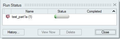
Click Run.
The run status is displayed.