
Add More Jobs to the Flow
A project is normally made up of many jobs that work together toward the goal of the project. A given job may depend on the output of another job, and in turn may create output that is needed by a downstream job. Each job must be run in the proper sequence in order to reach the project's goal.
Next you will add more jobs to this project to emulate that aspect of dependency. Continue to use the cp program to emulate all the various tools used in your jobs.
Job 1: TRANSFORM source-file expanded-file
Job 2: TRANSLATE expanded-file translated-file
Job 3: SORT translated-file sorted-file
Job 4: ARCHIVE translated-file archived-file
This reflects a project goal of creating two final result files that are formed by running processing tools in the proper sequence, based on a single input file.
Job 1: TRANSFORM aa bb
Job 2: TRANSLATE bb cc
Job 3: SORT cc dd1
Job 4: ARCHIVE cc dd2-
Emulate this project using cp with this job list:
Job 1: cp aa bb
Job 2: cp bb cc
Job 3: cp cc d1
Job 4: cp cc d2
This project has exactly the same dependency graph as the one above. We have emulated a complex project with this technique of using cp with simple, empty files. -
Add the extra jobs to the flow managed by FlowTracer to
register this larger project. Run the vw wrapper program with
the job command parameters that define the additional jobs. Execute these
commands:
% vw cp bb cc
% vw cp cc dd1
% vw cp cc dd2
This creates a flow that is getting more complex and has more dependencies for FlowTracer to manage. If file "aa" is changed then files "bb", "cc", "d1" and "d2" all become INVALID.FlowTracer will notice if that happens and mark the files as INVALID. FlowTracer can also schedule and dispatch the jobs to run in the proper sequence to make the INVALID files VALID.
At this point the graph should look similar to the one in shown below. Minor differences in the horizontal position of the nodes are to be expected.Figure 1. 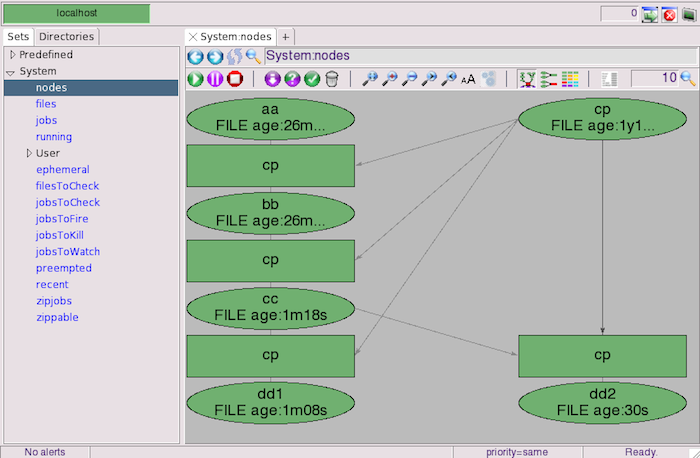
This demonstrates an interactive way to register jobs, but is not promoting this as the way to register jobs in a production environment. The intent is to demonstrate what the display of the flow graph looks like as a job is added to the flow. You have now seen how the data structure within FlowTracer holds the dependency graph between programs and files, how FlowTracer reports on the state of files using shapes and colors. You have seen how the FlowTracer GUI helps you visualize the state of the flow graph.