Learn how to set up a simulation model and equipment, and define the generation of
bulk materials using EDEM Creator.
To set up the model:
Select the units of measurement to be used throughout EDEM.
For more information about how to select units, see Select Units.
Click Tools > Options... and then select the Units tab.
In the Units tab, change the following measurement units:
Velocity to
m/s
Length to mm
Click OK.
Specify a title and description for the model.
Click Project in the Creator Tree.
In the Detailed View, specify a title (LEBM
Unconfined Compression).
Enter a description in the Description
field.
The model title and description is displayed in the Data Browser window. You
can close the Data Browser window to allocate more space for the windows that
will be used throughout this tutorial. If required, you can open the Data
Browser window again by right-clicking the menu bar and selecting
Data Browser.
Define the Bulk Material
The first step in setting up the model is to add bulk material and bulk material
particle shapes to a model and define their interactions.
To define the bulk material:
Add the bulk material.
Right-click Bulk Material in the Creator Tree,
select Add Bulk Material, and enter the name
Particle Material in the
BulkMaterial 1 highlighted field.
Alternatively, you can also use the icons in the Toolbar.
Define the bulk material properties and interactions.
Select Particle Material in the Bulk Material
section.
In the Particle Material Properties dialog box,
specify the Poisson's Ratio, and Shear
Modulus, and Density.
Define the bulk material interactions.
In the Interactions section, click the icon.
In the Select Material dialog box, select
Particle Material from the dropdown list and
ensure that the settings have the default values.
Create a new particle type.
Right-click BulkMaterial 1 and then select Add Shape from Library > Single Sphere.
Rename the particle to Bonded particle.
Set the radius of the sphere to 1.5 mm.
Select the Edit Contact Radius checkbox below the
Viewer Window.
A new column is displayed in the table as follows:
Set the value of the Contact Radius to
1.7 mm.
Set the size distribution of the bulk material.
In the Creator Tree, select Grain Particle > Size distribution.
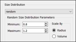
Select random from the Size
Distribution dropdown list.
In the Random Size Distribution Parameters
section, select 0.8 from the
Minimum list and 1.2
from the Maximum list.
Select Radius in the Scale
By section.
Navigate to Bonded Particle > Properties and select Calculate Properties
based on Spheres.
Note: In this tutorial, a bonded particles model is used.
When using bonded models, it is recommended to have a Contact Radius between
the particles greater than the Physical Radius. The Contact Radius is
important as it determines the area in which a bond can exist. When the
particles no longer overlap the bond information is lost.
A bond will be
formed in the first Time Step of the simulation only. After these
initial bonds have been created, no new bonds will be formed. Due to the
formation of bonds during the first Time Step, either the Volume Packing
tool can be used which creates particles prior to the first Time Step
starting (as detailed in this tutorial) or export a previous simulation
with particles already in place and the particles are created using a
Contact Radius (where possible) to allow for bonds to be created between
particles even when physically not in contact.
Define the Equipment Material
The next step in setting up the model is to add the equipment material which will be
used in the simulation.
To define the equipment material:
Add new equipment material.
Right-click Equipment Material in the Creator
Tree, and then select Add Equipment Material and
enter the name 'steel' in the highlighted field.
Define the equipment material properties.
Select Steel in the Equipment Material
section.
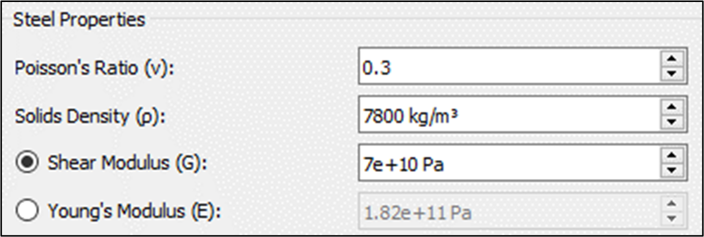
In the Steel Properties dialog box, specify the
Poisson's Ratio, Solids
Density, and Shear Modulus as
follows:
Define the bulk material - equipment material interaction.
In the Interaction dialog box, click the icon.
Select BulkMaterial 1 and then click
OK.
Ensure that the settings have the default values.
Define the Geometries
The next step in setting up the model is to define the Geometry used in the model.
To define Geometries:
Create the Loading plate.
Right-click Geometries in the Creator Tree.
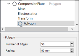
Select Add Geometry > Polygon and then enter the name
CompressionPlate into the highlighted field.
Expand CompressionPlate in the Creator Tree and
select the Transform subsection and set the Z
position to 100 mm.
Select the Polygon subsection and specify the
Number of Edges and
Dimensions of the polygon as follows:
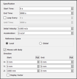
Right-click CompressionPlate and then select Add Motion > Add Linear Translation Kinematic.
Create the Base Plate.
Right-click Geometries to create a second
polygon.
Rename the polygon to GroundPlate.
Set the Number of edges to
50 and radius to
80 mm.
Leave the transform position to 0,0,0.
Create the particle factory.
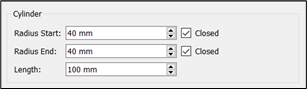
Right-click Geometries to create a cylinder and
rename to Particle factory.
Click Add Factory and select Dynamic
Factory.
Select the Transform subsection and set the Z
position to 50 mm.
Set the Radius Start, Radius
End. and Length as shown:
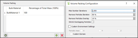
Right-click Particle factory to add Volume
Packing.
In the Volume Packing dialog box, click the
icon to add BulkMaterial 1.
Set the Imposed Solid Fraction to
60%.
Set the Start Time as 0
s.
In the Volume Packing Configuration section,
clear the Shrink Overlapping Particles checkbox
as follows:
Define the Physics
The next step is to select the contact models that describe how elements behave when
they come into contact with one another.
To define the Physics:
In this example, the default Hertz-Mindlin contact model
and Standard Rolling Friction are used for both Particle to Particle and Particle to
Geometry interactions.
Select Physics in the Creator tree.
Select Particle to Particle from the
Interaction dropdown list.
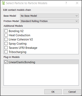
Click Edit Contact Chain.
Select No Base Model from the Base
Model dropdown list (replace this model with the Linear Elastic
Bonding model which includes the base component).
Select LinearElasticBonding and click
OK.
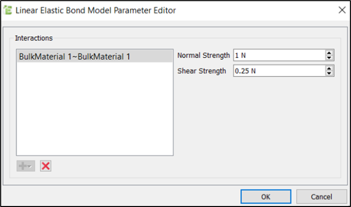
Select the LinearElasticBonding model and click the
icon to define the bonds.
Click the
icon and set the parameters as follows:
Optionally, to select a different model, click Edit Contact
Chain and select the required contact models.

 icon.
icon.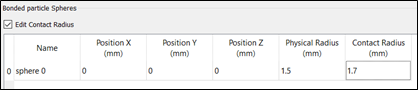

 icon to define the bonds.