Release Notes: Altair Feko 2026
Altair Feko 2026 is available with a long list of new features, corrections and improvements. Altair Feko 2026 is a major release. It can be installed alongside other instances of Altair Feko.
Feko is a powerful and comprehensive 3D simulation package intended for the analysis of a wide range of electromagnetic radiation and scattering problems. Applications include antenna design, antenna placement, microstrip antennas and circuits, dielectric media, scattering analysis, electromagnetic compatibility studies including cable harness modelling and many more.
WinProp is the most complete suite of tools in the domain of wireless propagation and radio network planning. With applications ranging from satellite to terrestrial, from rural via urban to indoor radio links, WinProp’s innovative wave propagation models combine accuracy with short computation times.
WRAP is a comprehensive tool for electromagnetic propagation, antenna collocation and spectrum management. WRAP combines propagation analysis, often over large areas with many transmitters and receivers, with system analysis to include complex non-linear equipment properties.
Highlights of the 2026 Release
The most notable extensions and improvements to Feko, WinProp and WRAP in the 2026 release are summarized here.
Salient Features in Feko
- Simulation times for large problems using MoM/MLFMM have been reduced dramatically. The impact is particularly large for models including ground planes and/or dielectric structures.
- The RL-GO solver used with point source and impressed antenna excitations has been
enhanced, delivering greater computational accuracy and achieving performance gains of up
to an order of magnitude in some cases.
Figure 1. Performance comparison between Feko 2025.1 and Feko 2026 for antenna placement studies. (A) a 2.3325 GHz SDARS antenna mounted on a vehicle solved using MoM/MLFMM (196855 elements; 24 processors; PEC ground). (B) A 10 GHz slotted waveguide antenna mounted on a ship solved using RL-GO with a spherical mode source representation (5742 elements; 40 processors; 13.8 GB required for all cases). 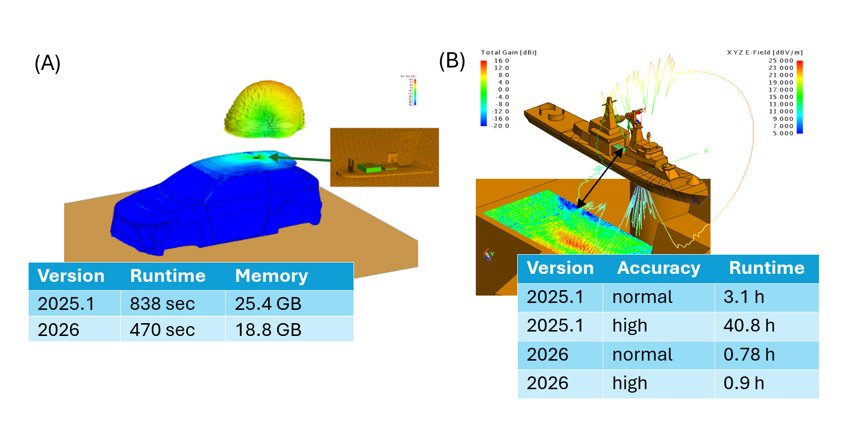
-
A new configuration type, the Reciprocal Excitation configuration, has been introduced. Simulations using this configuration allow the computation of load responses (voltages and currents induced at loads) under plane wave excitation to be derived as a post-processing step, using the Reciprocal Configuration application macro in POSTFEKO.
Figure 2. The new reciprocal excitation configuration in CADFEKO. 
This workflow offers a computationally efficient approach to many EMC immunity and receiving antenna analysis problems, where only one simulation to compute far-fields is needed per source and/or load point (all loads including cable harness loads and schematic link connections are supported). With this information, the voltages and currents induced at these points can be extracted and analysed for any incident plane-wave direction.Figure 3. An example of coupling into a shielded cable using the reciprocity feature. 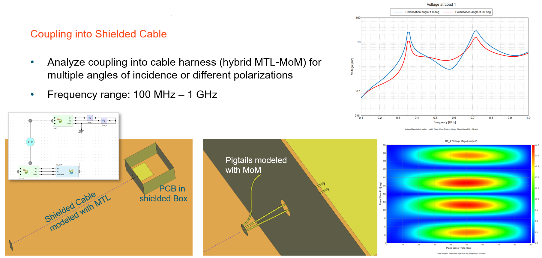
When analysing a direction-finding antenna array to determine port voltages as a function of direction of plane wave incidence, for example, the number of required simulations is reduced to the number of antennas × number of frequencies and is independent of the number of incident angles of interest. Incident plane wave properties - such as amplitude, polarisation, polarisation angle, and ellipticity - can be specified during post-processing.
- Thick coatings defined using multi-layered dielectrics are now supported on PEC
faces on the boundary of closed regions (previously, only single layer dielectrics could be
used in this way).
Figure 4. An illustration showing a thick coating consisting of multi-layered dielectrics applied to the surface oad a closed metalic (PEC) structure. 
-
The adaptive frequency sampling approach has been integrated into the Solver. This approach requires fewer license checks, creates the .fek file only once (PREFEKO) and performs model setup and geometry checking phases only once irrespective of the number of frequencies solved. Integration also avoids the need to store, read and manipulate .bof files on disk - which caused performance degradation as the number of frequencies increased. For simulations where any of the factors mentioned contributed significantly to the total simulation time, the impact can be very dramatic when compared to ADAPTFEKO used for adaptive frequency sampling in previous releases. Additional benefits (such as the ability to use adaptive frequency sampling with AMRFEKO) are also clear.
Figure 5. An example showing speedup by a factor 1.6 for a Vivaldi antenna in version 2026, when compared to version 2025.1. 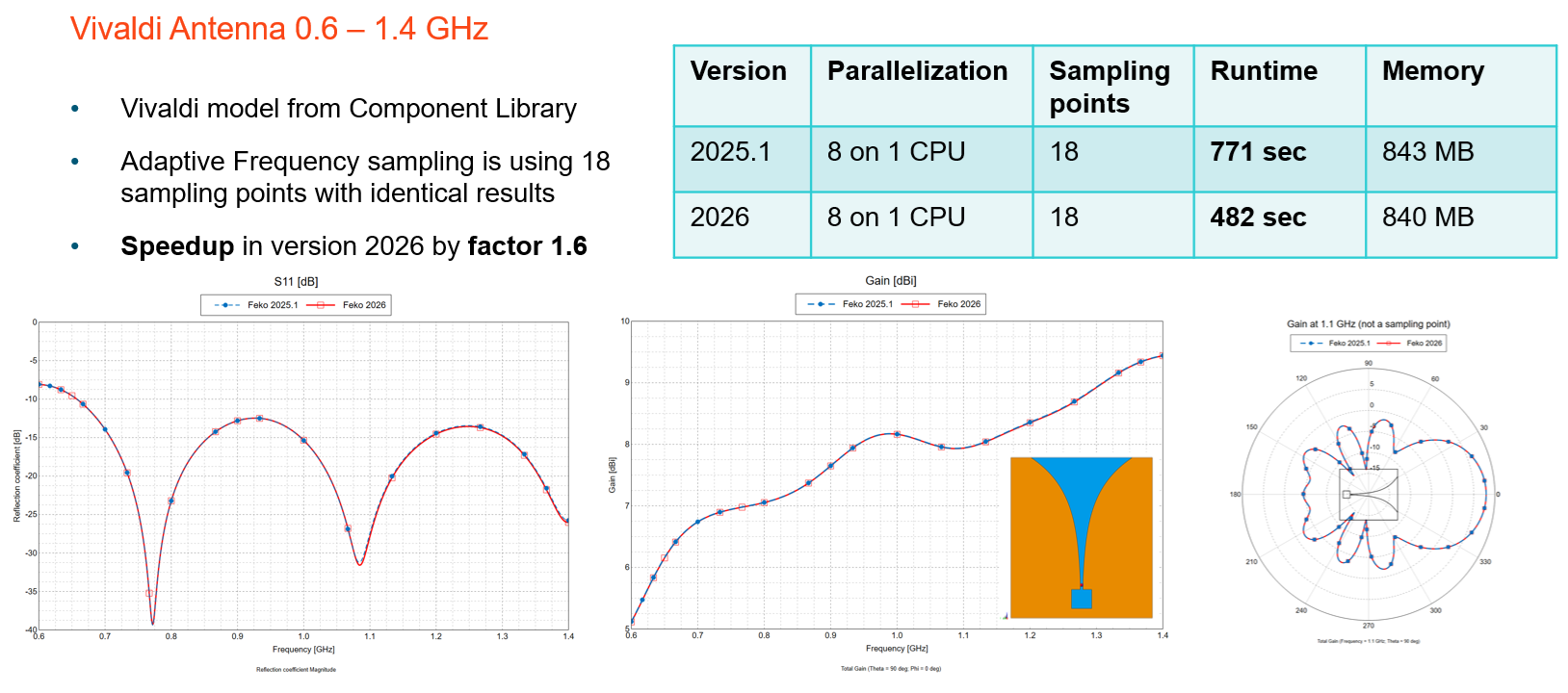
- The following enhancements have been introduced to cable modelling:
-
- Pin linking improvements
- The Create Cable Instance dialog now supports simplified
pin-to-pin connections:
- Sequential connection based on pin index order.
- Label-based connection use signal labels to match pins (e.g., Shield or Core).
-
- Circuit management
- Added options to remove or duplicate circuits connected to selected cable connectors. Duplicated circuits can be linked to another connector (even in a different harness) with an optional name prefix.
-
- Cable path creation
- Added support to create a cable path from continuous wires or edges, automatically combining them into a single path.
Figure 6. An example showing connections that were auto matched based on signal labels. 
-
- When importing PCB data from ECAD formats such as ODB++, media properties and definitions are now recognized and imported where possible. If exact material properties are unavailable, materials with logical names are automatically created, simplifying the setup of simulation projects after ECAD import. Additional improvements, including enhanced arc and via representations have also been made in the ECAD import process.
- The following POSTFEKO API extensions were made:
-
- Cable probe voltage data
- All voltage data computed using a cable probe can now be plotted on 2D plots and accessed via the API for automation. Previously, some voltages were unavailable for plotting.
-
- Multi-line tooltip notes
- Support added for multi-line text tooltips on stored data, which can also be set through the Lua API.
-
-
Remote job execution now supports configuring of a Microsoft Windows host to launch jobs on Linux servers using a PowerShell envoke mechanism.
Salient Features in WinProp
- Accelerated the SRT independently of the number of polygons, but can also be combined
with a precomputation for further acceleration.
Figure 7. Examples showing the acceleration. 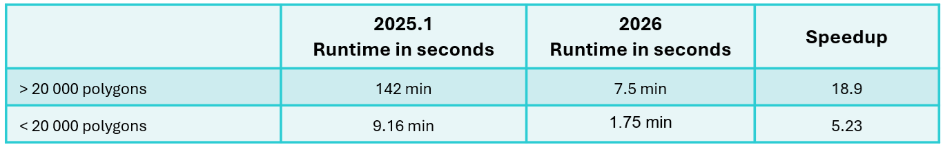
- Support was added for Pulse Radar which is a radar system that transmits short,
repetitive RF pulses to detect and track targets. Detection is achieved by measuring the
echo time delay (determines range) and Doppler shift (determines radial velocity). The
following waveforms are supported:
- Rectangular Pulse: simple but limited range resolution
- Frequency-Modulated Pulse: improves range resolution
- Phase-Modulated Pulse (Barker codes): offers good autocorrelation properties
Figure 8. An example of air traffic radar that provides range and radial velocity of aircrafts. 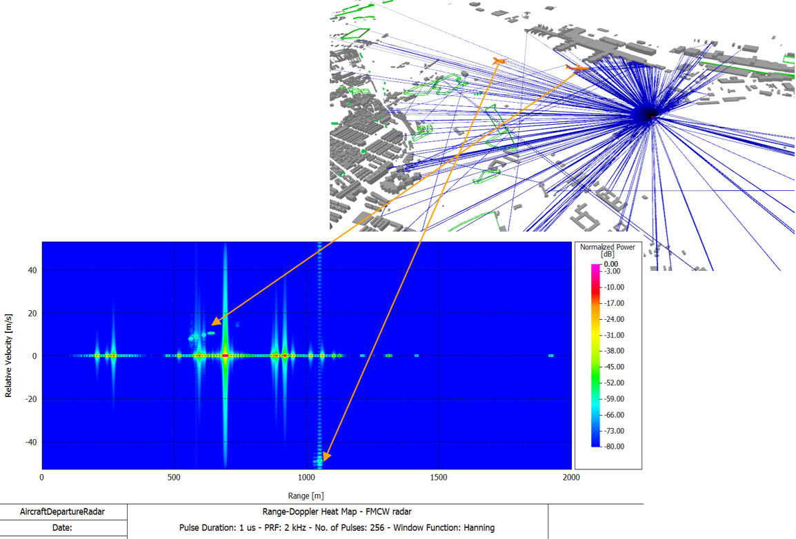
- The FMCW radar post-processing was extended to 4D radar, enabling it to provide range,
velocity, azimuth, and elevation information. This was achieved by adding the following extensions:
- Constant False Alarm Rate (CFAR) parameters used for target detection:
-
- Cell-averaging CFAR
- This algorithm can be used in most situations and estimates noise by averaging power from reference cells.
-
- Greatest-of cell-averaging CFAR
- This algorithm is typically used when it is important to avoid false alarms at the edge of clutter. It uses the higher average from leading or lagging reference cells to set a threshold.
-
- Smallest-of cell-averaging CFAR
- This algorithm is typically used when targets are closely located. It uses the smaller average from leading or lagging reference cells for the threshold.
-
- Order statistic CFAR
- This algorithm is a compromise between greatest-of and smallest-of cell averaging. It sets threshold based on a selected rank-ordered sample among reference cells.
-
- Option to display the Range Elevation (AoA) heat map for vertical angle estimation.
Figure 9. An example of a Range Elevation (AoA) heat map for vertical angle estimation. 
- Option to display the radar output as a point cloud. Each radar detection (range,
Doppler, azimuth, elevation) is mapped into a 3D point in the space, which provides
LiDAR-like visualization. Detection results in the point cloud depend on the defined
CFAR settings.
Figure 10. An example of radar output as a point cloud. 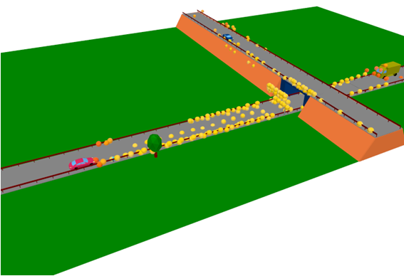
- Constant False Alarm Rate (CFAR) parameters used for target detection:
-
Bistatic RCS as given in the .ffe file format to replace individual objects (for example, RIS) is now fully supported in ProMan. Rays having reflections before or after the interaction at the bistatic RCS are supported, also rays via multiple bistatic RCS. The bistatic RCS can be plotted depending on the incidence direction for which the individual RCS has been computed.
Figure 11. Bistatic RCS as given in the .ffe file format to replace individual objects (for example, RIS) is now fully supported in ProMan. 
The bistatic RCS can now be plotted in ProMan, depending on the incidence direction.Figure 12. The bistatic RCS can now be plotted in ProMan. 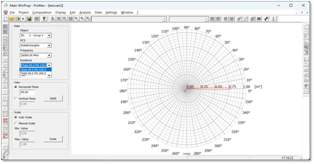
- Support was added to allow entering and exiting tunnels when being combined with pixel
topography in SRT/DPM.
Figure 13. Example of an environment with pixel topography featuring a tunnel entrance/exit, showing rays exiting the tunnel. 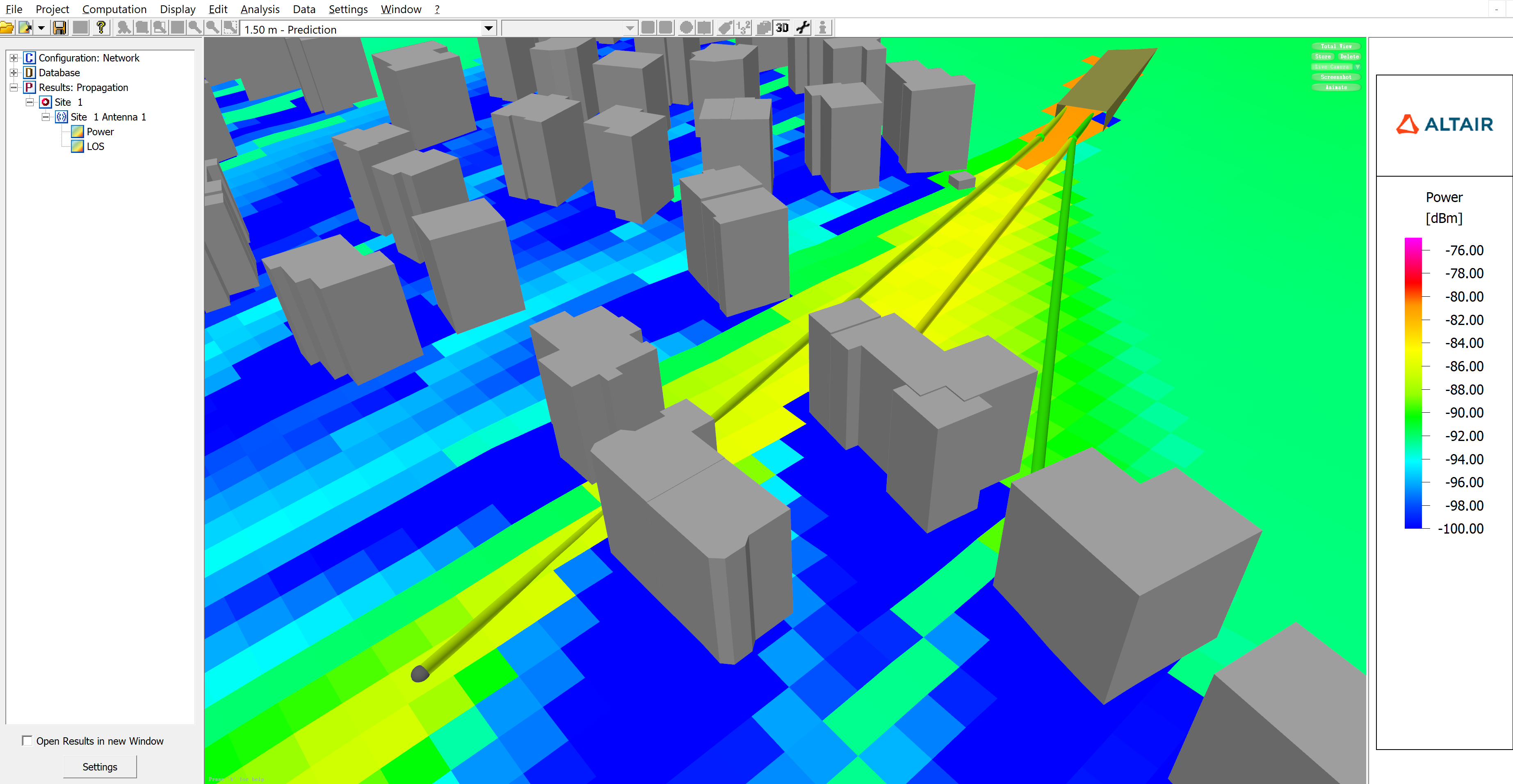
Salient Features in WRAP
- The XSD schemas for outgoing XML messages are now complete. A validation mechanism was
added to the output message before it is sent. The validation mechanism is disabled by
default. There are two independent options for validation:
- Display a pop-up window with the error message.
- Append the error message to the returned message in a separate element named ValidationError.
- Updated the frequency allocation tables in WRAP SAM as per ITU RR 2024.
Feko 2026 Release Notes
The most notable extensions and improvements to Feko are listed by component.
CADFEKO
Features
- Introduced the reciprocal excitation configuration for computing source data for specified source-load pairs. To use this setup, define the loads of interest and include a far field request. In post-processing, the induced load currents are calculated using the principle of reciprocity, where the far field angles represent the directions of incident plane wave excitations. This analysis can be performed in POSTFEKO using the Reciprocal Configuration application macro.
- Allow PMC faces to be on the outer boundary of FEM and VEP regions.
- Relaxed electrically thick coating limitation to allow multiple layers. Previously it was limited to only a single layer.
- Standardised load definitions on segment ports. All load types (series RLC, parallel RLC, and complex loads) are now written out as LZ cards to the .pre file.
- Implemented the functionality to create a cable path from selected wires or edges.
- The Create Cable Instance dialog now includes new options to simplify linking pins between source and destination cable connectors. Users can establish pin-to-pin connections in two ways:
- Sequential connection: Signals connect from the source connector to the destination connector based on pin index order, starting with the first pin on each connector.
- Label-based connection: The Find and connect pin names using signal labels option automatically connects signals between pins where the pin labels match the signal label. For example, a signal labelled
Shield
connects theShield
pin on the source connector to theShield
pin on the destination connector, and similarly, a signal labelledCore
gets connected between theCore
pins.
- Added zoom to selection for cable schematic probes when there is a active cable schematic view.
- Added a new placement mode when adding components on the cable schematic view that places the selected component type at the mouse cursor position. This aids the drawing of circuits by allowing quick placement of multiples of the same component, each placed with a single click at the desired location. The option supports using the keyboard shortcut R for rotating the component during placement. This placement mode is available in addition to the traditional way of clicking on the component icon on the ribbon to place a single instance of the component at the centre of the view, or at an offset from the centre if another component is already at that position.
- Added a new action that resets the position of the cable connector to the schematic path terminal on the cable schematic.
- Allow the connector spacing value on the cable schematic to go as low as 1%. Previously, the minimum allowed connector spacing was 25%.
- Added a new action to delete the circuit connected to a selected cable connector on the cable schematic view.
- Added a new action to duplicate the circuit connected to one cable connector to another cable connector (which may belong to another cable harness).
- Improved the performance of geometry change tracking. This is most noticeable when working with large models and making changes like applying media properties or performing Boolean operations (union/subtract) on entities from which faces or edges have been deleted.
- Improved CADFEKO mesh (.cfm) file writing to not use excessive memory when saving large meshes containing millions of elements.
- Improved stability by avoiding errors and crashes that could occur when topology is placed on top of other geometry while automatic meshing is enabled. These errors could surface during the input geometry preparation stage of meshing, within the Parasolid union process.
- Added a mechanism to prevent CADFEKO from crashing if the mesher crashes.
- An upgrade to the latest version of the meshing library brings the following improvements:
- Improved surface meshing robustness and responsiveness, resolving hangs and delays caused by complex topology edits, overlapping surfaces, and mixed curvature (for example, tight arcs with broad curves). This also addresses issues where background processes failed to cancel properly, sometimes showing Busy cancelling background processes.
- Enhanced curvilinear meshing accuracy on planar surfaces, ensuring better alignment with outer boundaries and improved edge conformity.
- Resolved crash scenarios during meshing triggered by undo/redo operations involving deleted or replaced faces on complex geometry.
- Refined Elongated triangles behaviour to prevent overly fine meshing in sensitive regions, including cylinder seams, PCB tracks, wire elements, and cylindrical cutouts like vias and bolt holes.
- Upgraded the Altair ECAD PCB import library bringing the following improvements:
- Support for reading media definitions from ODB++ files.
- Enhanced support for various ECAD formats.
- Improved arc representation.
- Multiple bug fixes.
- Via pads in the conductive signal layers are now imported as part of the PCB import process.
- KBL import previously supported connectors only at cable end points. It now also supports (splice) connectors placed along a cable path.
- Issue a model status error if a problem that is configured to be solved with an asymptotic method is too small relative to the wavelength for the high frequency approximation to be valid.
- Introduced a verification check that triggers a model status error when an edge port references a face that is specified to be solved with ray launching geometrical optics (RL-GO).
- Added a verification warning when applying coatings or skin effect when using RL-GO with edge and wedge diffraction enabled.
- Removed a verification check that incorrectly caused model status errors when using RL-GO with multilayer thin dielectric sheets.
- Added the following Lua methods to the Media object:
- ItemList returns a list of all media matching the given label.
- Contains returns True if a media with the given label exists.
Resolved Issues
- Fixed a model loading issue where primitive parts were not scaled correctly. Affected models now undergo a full re-evaluation during loading, which may increase loading times. Existing simulation meshes are no longer valid and re-meshing is required.
- Corrected a .pre file writing problem with the order of sources where adding other sources with a looped plane wave could have caused an error about an empty loop to be reported during simulation.
- Resolved an issue where the transformations of transformed plane wave sources were not written to the .pre file, and therefore not considered during simulation.
- Resolved an issue where incorrect loads and sources were being written to the .pre file when a topology port was connected to a network port via the schematic.
- Corrected .pre file writing for cable harnesses that use connectors defined by 3D coordinate.
- Resolved an issue where the shield radius for coaxial cables, as communicated to the Feko Solver, incorrectly included the coating thickness. The appropriate shield radius, excluding the coating thickness, is now written to the .pre file (SD card).
- Corrected .pre file writing for inactive waveguide ports.
- Media are now correctly included when the inactive waveguide port is specified on the surface of a dielectric.
- AW cards are no longer written out for inactive waveguide ports bounding tetrahedra (when the finite element method is used).
- Simulation meshes containing wire segments from models predating CADFEKO 2025.1 are now loaded with warnings instead of being skipped, even when they may not load correctly. Users are advised to re-mesh the model, but can review the mesh and choose to use it.
- Fixed incorrect triangle normals in simulation meshes caused by reversing normals and/or mirror transforms. Face normals, triangle normals and normal display could have been wrong when mirror transforms were applied to geometry parts, mesh parts, groups and protected models.
- Fixed a bug where face normals would not be correctly reversed.
- Fixed a rendering overflow problem when a model has many parts and many mesh elements.
- Fixed a problem where some wires in the symmetry plane would not be meshed.
- Fixed a bug where some wires on a symmetry plane would not be meshed for the special case where there are wires inside and outside a volume region.
- Resolved an issue where manually meshing a model with wires crossing the symmetry plane would not result in a simulation mesh.
- Fixed an issue where automatic meshing failed to trigger correctly when re-enabled after duplicating a meshed part.
- Corrected a problem where unlinking a mesh and then setting it to remesh would not trigger automatic meshing.
- Improved the meshing for FEM distributed line ports to imprint vertices at the distributed line start and end points. This prevents solver errors such as End point is out-of-bounds and A FEM line port must be contained inside a FEM region during simulation. Existing ports need to be modified for the changes to start taking effect.
- Added default values when performing a custom mesh with triangle edge length empty (not valid) to prevent a crash.
- Fixed a crash that could occur when merging model meshes.
- Fixed a problem with the ribbon that could cause a crash when clicking on the File menu.
- Resolved a crash while rendering an antenna array after a delete operation.
- Corrected a problem where importing points for an optimisation mask could lead to a crash.
- Corrected a problem where preventing the deletion of a face used by a work surface could cause application crashes.
- Corrected a problem with setting power and other settings to be specified per configuration. The problem could have led to an infinite loop in some cases that would cause the application to hang.
- Prevent a crash when executing TransformView from Lua scripts.
- Resolved a crash when modifying a NURBS surface during script recording.
- Improved the usability of the Create Edge Mesh Refinement dialog by allowing selection of geometry edges in the 3D view when the display is set to model view with mesh overlay enabled.
- Fixed a problem applying transforms to polyline mesh refinement rules. This issue could cause Zoom to Extents to zoom out excessively and could prevent Zoom to Selection from properly focusing on the selected mesh refinement rule in the 3D view.
- Fixed Send copy to functionality so that copying entities between configurations supports undo operations and properly registers the changes to the model.
- Fixed a problem where certain operations were incorrectly added to the undo stack, which could cause a crash after using Undo.
- Fixed a problem with the undo functionality that could cause an assertion failure. The issue occurred when the system reported an empty rollback list but still allowed the undo action.
- Fixed a problem with the undo functionality that could cause an assertion failure after running an application macro and then performing many undo actions.
- Corrected a problem where a union could have failed due to medium settings not being ignored when the wire changes into an edge.
- Allow to delete the last wire if there are faces in the geometry part.
- Improved error messaging when deleting items (for example, sources or ports) to clearly specify which entities cannot be deleted and what entities reference them.
- Resolved a regression that was inadvertently introduced in CADFEKO 2025.1 where hiding a region from the details tree did not work with tetrahedron mesh elements. This functionality now operates as expected.
- Removed the green preview from the view when the Imprint Points on Geometry dialog is open. This makes it easier to select points on the geometry for imprinting.
- Fixed a bug where values appeared updated in the GUI but were not actually updated internally. The bug was discovered in the far field optimisation goal dialog.
- Resolved a regression in CADFEKO 2025.1 where point entry of a variable or named point could have entered it on multiple fields of the dialog.
- Changed the Number of copies field on the Copy and Translate and Copy and Rotate dialogs from a text input to a spin box control, since this field only accepts integer values and does not support variables.
- The stitch, subtract, project and path sweep tools now initialise labels correctly when created inside a group.
- The Use Model Mesh option for model mesh parts is now disabled when FDTD is active. This option has no effect with FDTD as the entire model must be given a voxel mesh representation.
- Fixed a legacy converter issue that could cause model conversion to fail when parts had deleted edges.
- Fixed issues in the legacy converter related to deleted entities and transforms. Deleted entities could appear in a converted model if, in the original model, they were removed from a primitive before a transformation was applied.
- Fixed a legacy model converter problem where path sweeps were not converted correctly, resulting in incorrect geometry.
- Corrected an issue with CADFEKO model import where general network schematic components were imported without their connections. General network schematic nets are now properly imported from .cfx file. Additionally, schematic components in each imported model are repositioned to prevent overlap in the schematic view.
- Resolved an assertion failure during KBL import with an error message referring to KBLRouting. This could be encountered when a cable route is defined between cable connectors through more than one cable path.
- Improved loop detection during KBL file import. An error message gets issued that indicates which route contains a loop.
- Updated references from Mentor Graphics to Siemens for Xpedition and PADS in the PCB Import Tool. Mentor Graphics was acquired by Siemens in 2017, with the name officially retired in 2021.
- Improved the algorithm that determines the shortest path length for cable routing on the Cable Instance dialog to avoid cases where an invalid path was chosen.
- The Cable Instance dialog now displays pin names by their labels instead of their full paths. Since the dialog is opened for a specific context, the path information is redundant.
- Cable harnesses and schematic probes are now listed alphabetically in the model tree (Configuration tab).
- Resolved an issue where the cable harness solution could be changed to Circuit crosstalk without setting the solution method for the outer cable problem to the only valid option (MTL). The solver would fail with Error 53247: The combined MoM/MTL solution method is not supported when requesting a circuit crosstalk calculation. The MTL solution method now gets selected automatically on the cable harness dialog when cable coupling properties are changed to circuit crosstalk.
- Fixed a bug where clicking and dragging schematic elements would swap selection. This would result in the wrong component being moved.
- Cable connector pins without signals will only produce a verification warning if its terminal is used in the cable schematic.
- Fixed a calculation error in the verification check for anisotropic materials that falsely triggered the model status error The inverse of the permeability matrix is zero or close to machine precision.
- Added validation for transforms on workplanes to prevent circular references where the transform references the workplane that it transforms.
- Added validation that prevents creating solution coefficient sources without a corresponding solution coefficient data definition.
- Corrected the verification check that incorrectly generated a model status error when using planar apertures with characteristic mode analysis (CMA).
- Fixed the verification error Planar Green's Function apertures must be located on a ground plane defined using planar multilayer substrates so it no longer appears for excluded entities.
- Corrected model validation for FDTD when using model mesh parts (imported voxel mesh).
- Corrected model validation of FDTD meshes by correctly ignoring excluded entities.
- Fixed the following issues in the Generate antenna array application macro:
- Correctly populate the magnitude and phase of the waveguide sources if the excitation distribution is non-uniform.
- Add an S-parameter configuration when this option is selected.
- Fixed the following issues with the Create Edge Port for Finite Substrate application macro:
- The macro would fail if frequency was set per configuration in the model.
- The edge port size would be incorrect when the model unit was something other than metres and using the option to specify the edge port using the width (the distance between specified points).
EDITFEKO
Features
- Added the RT card for requesting the source data for reciprocal excitation configurations.
- LZ cards now support resistance, inductance and capacitance values for segment ports. Legacy LS and LP cards are still supported.
POSTFEKO
Features
- Added support for multi-line text tooltip notes on stored data.
- Discrete frequency data is now sorted correctly when associated with a continuous frequency configuration. Previously, discrete data values were associated with the incorrect frequency values in these configurations. This improvement ensures accurate alignment between discrete data and their corresponding frequencies.
- In Feko 2025, the reporting of cable voltage probe data to the .out file was extended for MTL harness signals in the outer sub-problem. This data is now available for plotting on Cartesian graphs.
- Added support for the new reciprocal excitation configuration. The application macro library has a new Reciprocal Excitation category containing the Reciprocal Configuration application macro that can be used to process reciprocal excitation configurations.
- Increased the maximum number of frequency points for Touchstone data export from 9999 to 99999.
Resolved Issues
- Fixed the loading of models with partial or incomplete results to prevent an assertion failure upon opening.
- Resolved an assertion failure when loading models with FEM line ports connected to general networks.
- Fixed a crash when reloading results for models with ports connected to general networks.
- Resolved an assertion failure when importing .efe and/or .hfe files using the GUI import dialog. The problem did not affect the API.
- Resolved a crash when exporting stored near field results if the axes in the dataset are in a custom order.
- Fixed a crash that could have triggered when the field that specifies the number of samples of a time signal was cleared or set to zero or one.
- Fixed a crash that occurred when plotting data containing NaN values on a Smith chart. The previous Subtract loading default value of 0+j*0 could cause division by zero, resulting in NaN values in the plotting data. Similarly, crashes could occur when entering zero in either the Reference impedance or the Subtract loading fields, or if the values in these fields became zero while typing or editing. The default value to subtract is now 50+j*0 and NaN values are filtered out before plotting to prevent these crashes.
- Fixed an assertion failure triggered when attempting to plot stored surface currents containing NaN values.
- Fixed a bug where an error message about Data out of sync would be displayed in some cases when opening a session file containing surface graphs.
- Fixed minor grid labels appearing on the opposite side of the graph when enabling reversed order graph labels.
- Corrected the null-to-null beamwidth annotation calculation for far field patterns that do not have multiple nulls in the pattern.
- Added missing support for spherical modes receiving antennas that used the option to let the Solver automatically determine the spherical modes approximation method. These receiving antennas were previously misidentified as far field receiving antennas and their orientation in the 3D view could be incorrect.
- Loading a .pfs file with a receiving antenna trace will no longer have the incorrect source selected if multiple receiving antenna requests are present in the same configuration and the first receiving antenna is not selected as the source. This fix could cause a receiving antenna trace to be missing for very old .pfs files (from FEKO Suite 6.3).
- Corrected the near field surface plot footer text to indicate the plotted quantity.
Solver
Features
- Add native support (much reduced overhead) for adaptive frequency sampling from within Feko.
- Support reading .str file solution coefficients when using adaptive frequency sampling.
- Add support for a reciprocity calculation.
- Enhance RL-GO solver algorithms for point source and impressed antenna excitations, delivering substantial computational accuracy while improving performance depending on the model complexity.
- Improve speed of all RL-GO field calculations
- Improve and optimise the connectivity search between segments and triangles to support MoM connection basis functions.
- Multiple GPU support for the CMA solver. Both factorisation and dense matrix-vector product are now fully accelerated on multiple GPUs.
- Extend the planar Green's function option to allow for finite thickness PEC/PMC ground layers.
- Extend the planar Green's function method to support perfect magnetic conductor (PMC) triangles.
- Extend VEP with tetrahedra to allow perfect magnetic conductor (PMC) triangles in the model.
- Extend higher order basis function (HOBF) support to allow perfect magnetic conductor (PMC) triangles.
- Support PMC modelling with the hybrid FEM/MoM.
- Improve the auto (default) element order applied for the FEM. Previously this option always resulted in second order elements. In the 2026 release the FEM element order is determined per region, based on the electrical size of mesh elements over the frequency band of the simulation. First order elements are now applied to FEM regions with electrically extremely small mesh elements.
Resolved Issues
- Ensure that results which should be zero in UTD solutions are exactly zero, to avoid the impact of numerical noise on adaptive frequency sampled results.
- MoM antenna coupling to UTD structures is improved for antennas attached to UTD geometry where multiple types of ray effects contribute.
- Optimised ray file export for the RL-GO solver, achieving significant storage reduction of up to 50% for ray files depending on the model complexity and materials used.
- Manually specifying the PBC phase shift over a frequency range give incorrect array patterns. The phase shift incorrectly changed sign for consecutive frequencies.
- Fix a scaling problem with the calculation of continuous far fields for a finite MxN PBC array.
- Improved robustness in preparing interpolation models for representing tangential E/H-fields from wideband near-field data. These enhancements prevent excessively long or indefinite processing times during near-field computation.
- Fix scaling of finite array geometry in a standard MoM frequency loop configuration.
- Fix a potential deadlock for the parallel FEM/MoM when the direct sparse solver is used.
- Improve checking if an edge or vertex port is positioned correctly w.r.t. the normal vectors on a CFIE/MFIE/thick coating body.
- Triangle connectivity information is used to improve the algorithm that checks for closed dielectric regions (either SEP, FEM or RL-GO).
- Improve the spherical mode receiving antenna auto option so that a far field approximation is used when this is sensible.
- Fix internal error 48598 when a characteristic modes configuration is followed by an S-parameter configuration.
- Reported CPU timings are an average over all processes and threads executed on the first node.
- Fix an internal error when a waveguide port is defined on a dielectric surface equivalence principle region in finite array geometry.
- Suppress creation of the .mdp archive when in --check-only mode.
- Fixed an incorrect percentage progress reported during the near field aperture to spherical mode transformation phase.
- Optimised the power calculation phase for radiating sources. This phase may have resulted in excessive runtime for models consisting of a large numbers of elementary dipoles.
- Improve stability of GPU RL-GO ray tracing results.
Shared Interface Changes
Support Components
Feature
- Upgrade of Intel MPI to version 2021.16.1 on Windows and Linux.
WinProp 2026 Release Notes
The most notable extensions and improvements to WinProp are listed by component.
ProMan
Features
- Accelerated the SRT for large projects independently of the number of polygons.
- Added support for combining tunnels with pixel Topography in Indoor SRT / DPM.
- Added support for the SRT to stop MPI computation if an error occurs.
- Added support for Pulse Radar which is a radar system that transmits short, repetitive RF pulses to detect and locate targets. Detection is achieved by measuring the echo time delay (determines range) and Doppler shift (determines radial velocity).
- Added a button to invert the points of a leaky feeder cable on the Coordinates dialog. Using , you can quickly create an additional leaky feeder cable with the radio head on the opposite end.
- ProMan now fully supports bistatic RCS as given in the .ffe file format to replace individual objects, for example, reconfigurable intelligent surfaces (RIS). Rays having reflections before or after the interaction at the bistatic RCS are supported, as well as rays via multiple bistatic RCS. The bistatic RCS can be plotted depending on the incidence direction for which the individual RCS has been computed.
- The FMCW radar post-processing was extended to 4D radar, enabling it to provide range, velocity, azimuth, and elevation information.
Resolved Issues
- Fixed an error that could occur when generating a report in Microsoft Word if the language preference was not set to English.
- Fixed a crash when using MIMO network planning with external interferer.
- Fixed topo height for animation of time-variant prediction points.
- Invalid rays are now avoided, including interactions with monostatic RCS.
- The ground reflections on pixel topography are now computed for the full area when using the SRT propagation model.
- For handover simulation with 0ms TTT, the same cell assignment results are now achieved, similar to the static handover case.
- The number of MIMO streams is now limited to the number of Rx antenna elements. For example, in the case of 4 MIMO streams transmitted at base stations with 2 antenna elements at the mobile station, only the first two MIMO streams are received.
- Resolved display issues related to the Doppler heat map.
- Fixed an issue where absolute building heights were displayed incorrectly in the 3D view for urban vector databases (.odb file).
- When converting geodetic topo maps to UTM it might happen that stripes of the rectangular topo area might have topo pixels not defined, which gives a missing topo error for transmitters outside the topo map e.g. satellites. This is fixed now by moving the virtual transmitter further into the topo map.
- Extended the GPS antenna names by including the site ID to prevent duplicate names for different time steps.
- Resolved a crash that could have occurred when using the DPM propagation model and running out of memory.
- Fixed a bug where rays were not shown when clicking on the result pixels during the display of prediction planes.
- Fixed an issue where progress was reported incorrectly when using the SRT with scattering enabled.
- Fixed problems for the display of the Tx and Rx antenna patterns in 3D view.
- Fixed an interpolation problem for antenna gains at direction theta = 180 degrees (pointing to the ground).
- Added a check if the selected clutter map covers the defined prediction area.
- Fixed an issue where repeaters were ignored in the network planning analysis for rural scenarios.
- Resolved an issue where group IDs were not imported for .ida files.
- Resolved an issue where importing geo-coordinate measurements into a result incorrectly used the UTM zone from the measurements instead of the result. This could have led to incorrect coordinates in cases where the coordinates are at the border between two different UTM zones.
- Added support to display the vegetation interaction points in the case of vector vegetation.
- Resolved an issue causing artifacts in the ground scattering results for the SRT.
- Corrected the display of the prediction rectangle area in 3D by accounting for the topography height scaling factor.
- Avoid display and computation problems for antennas with 90 degree downtilt.
- Fixed a problem for the conversion from geodetic (long/lat) to UTM coordinates which resulted in gaps between neighboring tiles.
WallMan
Features
- Added support to convert CityGML databases with Level-Of-Detail (LoD) 2 to urban building database.
- Accelerated the saving of large urban databases.
Resolved Issues
- Fixed issues with importing topo and clutter maps in MSI Planet index format.
- Fixed a crash when converting a .glb file in WallMan that contains group names exceeding the maximum length limit of 128 characters.
- Fixed a crash that occurred when importing a faulty .dxf file.
- Resolved an issue where group IDs were not imported for .ida files.
AMan
Feature
- Added import filters to AMan for Huber+Suhner 2D and 3D antenna pattern formats.
Resolved Issue
- Fixed a crash in AMan when hiding/showing the command window.
Application Programming Interface
Features
- The conversion process now supports material assignments when converting urban building data to the ASCII ODA format when using WinPropCLI.
- Added support in the API for multiple mobile-station antenna configurations in a project for point and trajectory mode.
WRAP 2026 Release Notes
The most notable extensions and improvements to WRAP are listed by component.
General
Features
- The altitude value in the coordinates in the kml file exported from WRAP is now set as the calculation height.
- The margin added to calculation area in Radar Coverage calculations has been modified, which will affect the resolution used in the calculations. This improves the alignment between the resolutions used in Coverage calculation and Radar Coverage calculation Tools for the same calculation area.
- Corrected the progress bar and added function to cancel calculation for ObsMan method 1. The operation is now similar for the Method 1 case.
- Frequency Allocation Tables in WRAP SAM have been updated as per ITU Radio Regulations 2024.
Resolved Issues
- Import of TCT files has been corrected.
- Resolved an issue in Composite Coverage calculation which may lead to "NaN" values in some cells.
- Imported radar coverage results are now shown under the Radar Coverage Results folder in the Project tree.
- Modified the Clearance calculation methods to prevent running into an endless loop.
- Resolved an issue which may result in -inf for signal strength calculation on a long propagation path.